Research Article
UGV for the process of Drying Coffee on Patios
Department of Industrial Engineering, Federal University of Bahia, Brazil
2Department of Chemical Engineering, Federal University of Bahia, Brazil
*Corresponding author: Ricardo de Araujo Kalid, Department of Chemical Engineering, Federal University of Bahia, Brazil, E-mail: kalid@ufba.br
Received: August 24, 2019 Accepted: September 23, 2019 Published: October 3, 2019
Citation: Araujo YN, Kalid RA, Pires T Jr. UGV for the process of Drying Coffee on Patios. Int J Robot Res Appl Autom. 2019; 1(1): 18-25. doi: 10.18689/ijra-1000104
Copyright: © 2019 The Author(s). This work is licensed under a Creative Commons Attribution 4.0 International License, which permits unrestricted use, distribution, and reproduction in any medium, provided the original work is properly cited.
Abstract
This paper reports on the conception of an unmanned ground vehicle (UGV) technology to the process of drying coffee. This project aims at improving the drink and drying quality, in addition to reducing the production overheads. The proposed method involved a UGV, more specifically, an autonomous grain spreader (AGS), powered by electricity and guided by an electromagnetic field, which was induced by a wire buried below the surface of the yard and detected through inductive sensors. A microcontroller was used to process and exploit the the analog signals generated by the sensors and to channel the robot on a predetermined route. It was concluded that the implementation of this project can potentially enhance the drink and drying quality of the beans, thereby, offering a state-of-the-art mechanism in the technology of drying coffee on patios.
Keywords: Robot; Unmanned ground vehicle; Drying; Coffee; Patio.
Abbreviations: AGV: Automatic guided vehicle system; UGV: Unmanned ground vehicle; PID: Proportional integral derivative.
Introduction
Coffee is undoubtedly one of the most consumed products in the world, between 2013 and 2018, world coffee consumption exceeded 148 million 60-kg bags per year [1]. According to the Brazilian Specialty Coffee Association (BSCA), there are approximately 350,000 coffee farms in Brazil and only 10%, or 35,000 of these, are certified [2]. Brazil ranks highly among the worldʼs coffee consumers, second only to the USA, which consumes (on average) 24,690 million bags annually [1,3].
The costs of labor and drink quality associated with coffee production are a major challenge, primarily because they directly affect the final price of the product. Thus, producers have attempted to implement new automation technologies that offer competitive prices in the market. Therefore, in this study, an unmanned ground vehicle (UGV) is developed, which is the first automated robot that replaces human labor in the drying process.
Owing to extended periods of exposure to intemperate weather, rural workers suffer from the intensity of the sunʼs rays. This can lead to negative health effects, such as skin cancer and other physical ailments [4]. Moreover, drying coffee on patios requires a large amount of labor that increases the production costs.
In this context, the fundamental objective of this study was try to develop a reliable solution by coalescing knowledge of electronics, electromechanics, and automation to solve the problem of quality and the excessive labor (and related costs) in the coffee drying process.
The coffee used in this research is Arabica coffee. This type of coffee usually undergoes thorough care from farming to bagging. This results in a coffee with complex notes and higher market value [5].
Process of drying coffee on the patio
Drying is one of the most important elements in the coffee preparation process. The drying process begins after the fruit is harvested, and it can be performed on a drying patio under the sun or with mechanical dryers. In the drying process, several factors contribute to the quality of the beans. These include the way the beans are shifted on the patio, the amount of grains husked or harmed during drying, and the moisture levels that the beans must attain, during and after the process. The ideal process is to use the slowest drying speed without grain fermentation. It is ideal to shift the coffee beans at least ten times per day, to avoid fermentation [6].
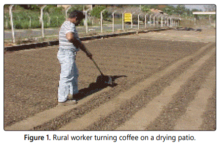
Patio drying is the most commonly used method by Brazilian producers, owing to its low cost [6]. In this method, the coffee is spread in small layers on a drying patio and repeatedly turned with a shovel, until the fruit reaches the ideal moisture content (Figure 1). In addition, machines such as motorcycles and tractors equipped with shovels are used to shift the coffee beans (Figure 2).
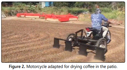
However, unlike the robot proposed in this study, these machines are heavy and peel the coffee. Moreover, machines require fuel and have relatively high operating and maintenance costs when compared to UGV. They also pollute the environment and coffee beans, with pollutant gases from combustion. The robotic system developed in this paper is the first mechanism capable of completely automating the coffee drying process on the patio, thereby reducing production labor costs, without polluting the coffee beans and improving the quality of the final product [7].
Materials and Methods
Creation of the robot
A robot is an autonomous system that exists in the physical world that can sense its environment, and act on it to achieve certain goals. Furthermore, an autonomous robot acts based on its own decisions and is not controlled by a human [8].
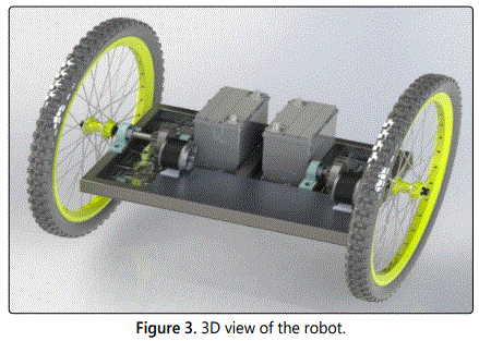
In accordance, the proposed robot was developed to behave autonomously; that is, it could act independently without any human intervention. The figure 3 shows a 3D view of the mechanical part of the UGV.
Chassis: The metallic components of the chassis were manufactured from mild steel tubes with a welded seam in a square or rectangular shape. The chassis consisted of six metal bars each with dimensions of 30 mm × 50 mm and thickness of 2 mm, sized and welded in position, as shown in figure 4.
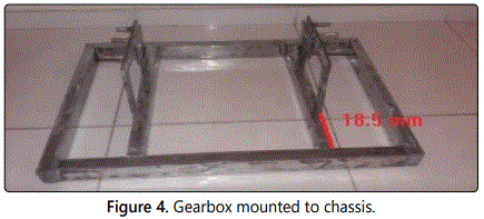
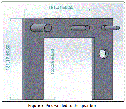
Reduction gearbox: Figure 5 shows the mounting of the reduction gearbox, responsible for increasing the torque generated by the robot. The gearbox was then welded to the chassis, as shown in figure 4.
Motor: Two 250 W motors were used. The ratings of both the motors were 3000 rpm and 24 V supply voltage. It was therefore necessary to use two 12 V 60 Ah batteries for each motor. A prototype was used in previous tests to verify the power required for the robot to shift the coffee beans. It became apparent that these motors would meet the power requirements.
Gears: The gears were dimensioned in the software package Solid Works, as shown in figure 6.
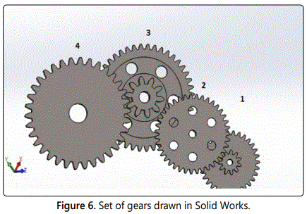
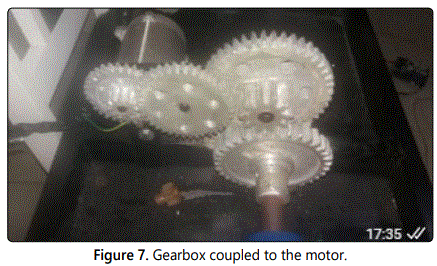
The gears were numbered from 1 to 4 in the order of smallest to largest. The reduction ratio of the gears, by division of their respective radii, was presented as follows: first ratio (41.25/15), second ratio (51.25/16.25), third ratio (69/18), and fourth ratio (72/27). Dividing the engine speed of 3000 rpm by this ratio yielded the following: 3000/((41.25/15) × (51.25/16.25) × (69/18) × (72/27) × 60)=0.564. Thus, the wheel axis measuring 320 mm in diameter would rotate at an angular velocity of 0.564 Hz (Figure 7).
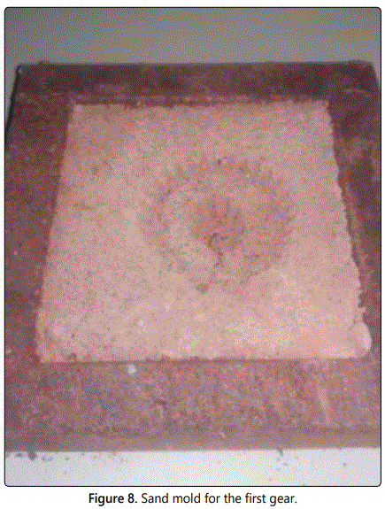
Casting: The gears were then made by casting, a highly costeffective process, in which the aluminum was melted and then placed in a sand mold to set [9]. Figure 8 shows the sand mold used in the experiment.
It was necessary to develop a preliminary model of the part, and for this a 3D printer was used to replicate the gears that were designed in Solid Works, as previously noted. The modeled gears were input into the 3D printer software and were manufactured using acrylonitrile butadiene styrene (ABS) plastic.
3D printing was typically used in rapid prototyping and additive manufacturing (AM). Objects could be of almost any shape or geometry, and were typically produced using digital model data from a 3D model or other electronic data source, such as an STL file [10].
The figure 9 shows the ABS plastic model, cast gear, and printer used in the manufacturing process.
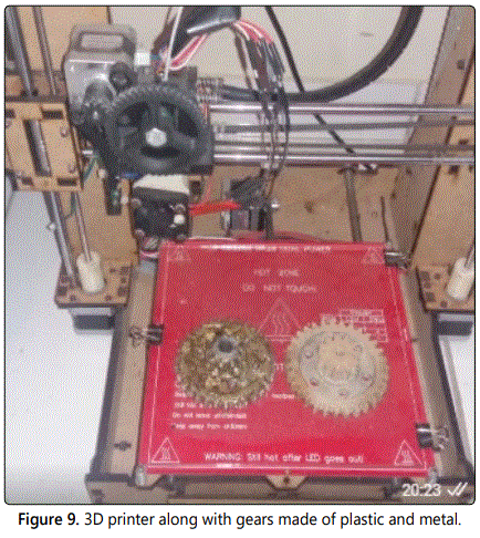
It is to be noted that the gear looking almost brown, on the left side in figure 9 was covered with grease. It is Gear 1 shown previously in figure 6, cast in aluminum. The other gear was made using the 3D printer.
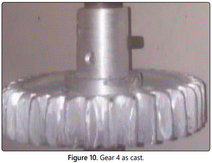
The same process was repeated with the remaining gears. Figure 10 shows Gear 4 manufactured using the same process.
Coffee stirring mechanism: As the coffee beans were shifted in the yard as part of the drying process, it was necessary to create a mechanism of “shovels”, so that the coffee beans could be shifted effectively on the patio, to dry them using solar radiation.
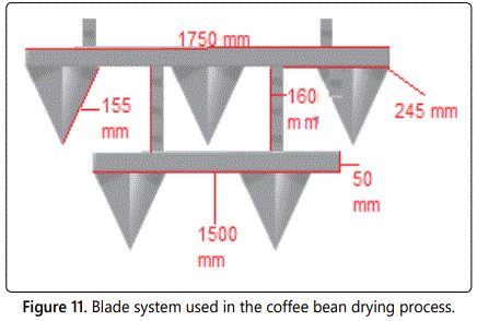
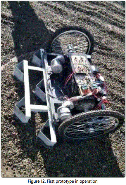
The shovels were built using a steel plate with a thickness of 2 mm, and the structures which were coupled to the blades were made with the same metal product used in the chassis of the robot. Figure 11 shows the dimensions of this mechanism. Figure 12 shows the developed robot.
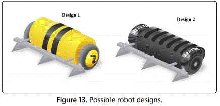
A video of the prototype in operation has been created and attached in this article [11]. A couple of more attractive and appropriate future designs that could be implemented for the robot are shown in figure 13. A construction of the mechanical parts with more details has been created [12].
Electrical design and standalone navigation system for the robot Arduino microcontroller kit: The Arduino platform was chosen to control the circuit as this was a prototype and Arduino platform offers ease of programming. However, the components could be replaced, to build a more robust and reliable electronic circuit [13].
An Arduino is a tiny computer that can be programmed to process inputs and outputs between a device and external components connected to it. The Arduino is a physical or embedded computing platform that can interact with its environment using hardware and software system [13].
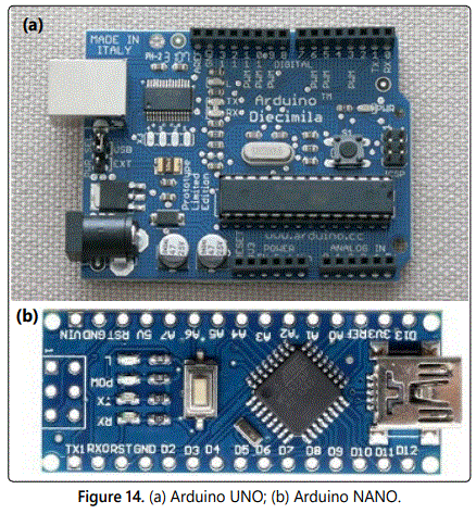
There are different types of Arduino microcontroller kits that offer a wide range of functionality. In this study, the Arduino UNO and NANO were used as shown in figure 14.
According to the manufacturer, Arduino was a free electronic hardware prototyping platform designed around a single-board Atmel Advanced Virtual RISC (AVR) microcontroller, with built-in input/output support, and a standard programming language derived from the programming language, Wiring (essentially C/C ++) [14].
Battery: The equipment had to be provided with an electrical power supply that would power all devices in use, such as motors and sensors. This was coupled to the structure. The battery used had to provide enough energy for the robot to function for a specific time period. Batteries varied in voltage, current, and power. The motor was powered by two sealed 12V, 60 Ah batteries.
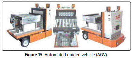
Autonomous navigation: After intensive research it was concluded that, for the robot to autonomously follow a predetermined path, with the required accuracy, reliability, and low operating cost, it would be necessary to use a method known as magnetic navigation that is widely used in automated guided vehicle (AGV) (Figure 15).
Conceptually, the idea of AGV was to replace the pilot of an industrial transport vehicle with software that could follow routes, load, and unload without the need for direct human interaction. In practice, they could range from small lightweight equipment to large structures that could move metal coils and other heavier materials [15].
In the Axter, Automationʼ article we can see the robustness and reliability accuracy of this method [16]. The figure 16 illustrates this process applied on UVG.
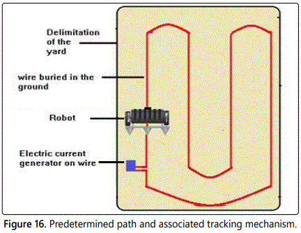
The red line represented a copper wire buried in the yard, which had a resistance of 34 Ω and the average current in the wire was 0.35 A. The blue rectangle represented a voltagegenerating circuit connected to the poles of the wire, thus making it possible to create a variable magnetic field in the wire, as shown in figure 16.
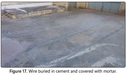
The figure 17 shows the practical implementation, where the floor was cut, the wire was placed underneath it, and finally covered with mortar.
Electrical circuit: A circuit consists of electrical elements connected together. Engineers use electric circuits to solve problems that are important to modern society [17]. The purpose of the electric circuit was to allow the robot to follow a predetermined course, shifting the coffee on the porch, along the way.
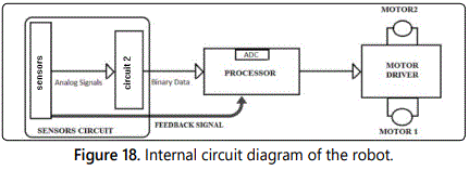
The circuit responsible for keeping the robot on the path existed inside the robot, and the working of this circuit is shown in figure 18. The entire circuit of the robot was divided into three small circuits and attached in the article by Araujo [18].
Sensor: This variable field was picked up by a pair of coils (sensors) installed in the robot. The sensor is a device that receives stimulus and responds with an electrical signal [19] (Figure 19).
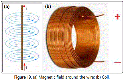
It should be noted that the intensity of the magnetic field generated by the current in the wire was proportional to the distance between it and the sensing coil, because the closer the coil moved to the wire, greater was the induced current in the coil. This was due to a physical phenomenon described by Faradayʼs law: The electromotive force generated in a coil is equivalent to the variation of the magnetic flux that passes through the coil, divided by the variation in time.
ε=∆Φ/∆t
The coil was composed of 400 turns of copper wire and its interior was composed of a ferrite core. The coilʼs inductance was 12.4 uh.
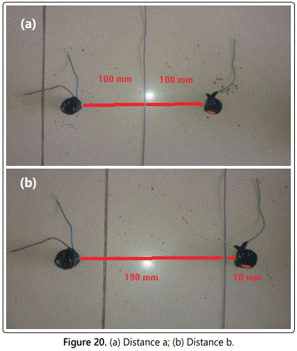
The figure 20 shows two variations in distances from the sensors to the wire. The coils were coupled to the central part of the robot, as described earlier in the paper.
The purpose of the circuit was to control the robot to ensure that the coils were always equidistant from the wire, as shown in figure 20a. This would indicate that the robot was moving along the length of the guide-wire. A possible situation in which the coils were ata different distance from the guide-wire is shown in figure 20b. In this case, the robot would have to move to the right to regain equilibrium condition, as shown in figure 20a. A detailed control circuit is presented later in the document.
Programming
Microcontrollers are typically programmed in high-level languages. One of the essential tools needed to program a microcontroller is an integrated development environment (IDE). The creators of the microcontroller usually develop this software [20].
Proportional integral derivative controller: Before addressing the Arduino UNO programming, it is necessary to address a control method used in automation called proportional integral derivative (PID) control.
To efficiently control the system, a PID controller was used. This allowed the robot to detect route errors, if there were any, and to determine the next steps to stay on track. PID control had been implemented in other autonomous vehicles due to its effectiveness [21]. PID was widely used for process control in various engineering sectors, including automotive, aerospace, electrical, mechanical, hydraulic, chemical, and thermal [22].
In this study, a proportional control algorithm was developed to make the robot follow the wire with greater stability. As noted earlier in this paper, a voltage was generated which was proportional to the distance from the coil to the wire. Therefore, a program capable of converting this voltage into a binary number, representing the distance from the coil to the wire, was required. Subsequently, this would send an electric current to the motors that corresponded to the distance, to control the direction of movement of the robot. Because there were two coils, these distances would be subtracted from each other, always from the right coil to the left, and this would direct the robot to the left or right, to keep it parallel to the wire. The figure 21 illustrates this process.
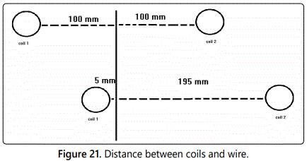
Figure 21 represents two possibilities that could occur in terms of coil location, with respect to the buried guide-wire. In the first possibility, the following condition was applied:
100-100=0
Thus, the two motors would operate at their maximum speeds. In the second possibility, the following condition was applied:
195-5=190
The algorithm would thus cause the Arduino to decrease the right motor voltage proportionally to 190. The algorithm shown below was encoded onto the Arduino UNO.
Programming Algorithm: The figure 22 shows the simplified flowchart of the control algorithm implemented in the robot.
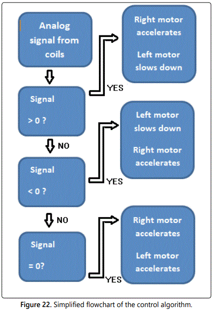
The complete algorithm implemented in the Arduino IDE has been created [23]. It could be observed that the PID controller caused a voltage to be generated at the motor poles, as a function of the distance from the coils to the center of the wire, causing the robot to follow the direction of the wire buried in the yard or patio. Consequently, the robot was forced to follow a predetermined path.
Results
Cost
A price quote was created with a renowned company selling motorized coffee drying bikes called Rodomoto [24]. It was observed that on average, a motorcycle costs approximately 1636.98 USD plus the labor cost needed for operation by a worker. The minimum wage in Brazil, as of the date of this article and according to the Labor Guide, is 240.07 USD [25]. In contrast, the construction of the robot was approximately 962.93 USD, plus the energy costs associated with operation. The robot does not use a combustion engine, so it is estimated that an electric motor is more economical under the same drying conditions and requires less maintenance.
Quality
Previously in this article, it was shown that the quality of the drink is greatly affected by grain peeling [6]; therefore it can be inferred that because the robot is significantly lighter than the motorcycle, it will certainly improve the quality of the drink.
Additionally, for the bean to dry optimally, the drying speed must be as slow as possible [6]. Finally, the robot will turn the coffee beans a precise number of times. This would be done by programming the robot with a low-speed algorithm that would certainly be a tedious job for a human to perform.
Final considerations
The robot presented here is much weaker than the motorcycle; one way to compensate for this would be to add more powerful electric motors, even if it is assumed that the robot has a speed of exactly half a meter per second; in 8 hours, it can travel a distance of about 14000 meters, which meets the need for many yards or patios. Larger robots can be designed to meet the demand for larger patios. It is also important to note that because motorcycles are manufactured for another purpose, the power of the motorcycle will surely be excessive for many types of yards.
It is intended that in future research, these estimates are made more rigorously after careful study, which is difficult now due to how recent robot technology is. Calibrated measuring devices and by following all rules and standards assigned to each measurement will result in a careful statistical comparison between a motorcycle, a robot, and labor in the sense of cost and grain quality after the drying process is complete [11].
Conclusions
It was certainly possible to create a UGV robot to reduce the costs of coffee drying on the patio, which had posed significant challenges for coffee producers in Brazil and many other countries. In addition, the proposed machine possessed a light mechanical structure, it would not peel the beans, thereby ensuring quality of the coffee. Additionally, it confirmed to the ideal drying speed, thus ensuring more homogeneous drying. In the future this robot can also be used for drying other grains such as rice, cocoa and others.
Author Contributions
Conceptualization and algorithm development was done by R.A.K and T.P.J, and development of the mechanical and electrical part of the robot was done by Y.N.A.
Funding
This research received funding from EletromóveisNossoLar.
Conflicts of Interest
The authors declare no conflict of interest.
References
- International Coffee Organization. World coffee consumption. Accessed on 13 August 2018.
- Ferreira C. Brazil has over 35,000 certified coffee farms. Revistacafeicultura.
- International Coffee Organization. Total production by exporting countries. Accessed on 13 August 2018.
- Cezar-Vaz MR, Bonow CA, Piexak DR, Kowalczyk S, Vaz JC, Borges AM. Skin cancer in rural workers: nursing knowledge and intervention. Rev Esc Enferm USP. 2015; 49(4): 564-571. doi: 10.1590/S0080-623420150000400005
- Abranches JL, Soratto RP, Perdoná MJ, Parecido RJ. Arabica coffee response to rates of coated and conventional urea in sandy soil. Pesq Agropec Bras. 2019; 54: e00767. doi: 10.1590/s1678-3921.pab2019.v54.00767
- de Mesquita CM, de Rezende JE, Carvalho JS, et al. Coffee Manual Harvesting and Preparation (Coffea arábica L.). Belo Horizonte: EMATER-MG. 2016.
- Cruz JS. Design of a coffee maker attached to a motorcycle. University graduate-engineering, Utfpr, Paraná. 2017: 62.
- Mataric MJ. The Robots Primer. 1st edition. MIT Press. 2007.
- Rubio JCC, Panzera TH, Nogueira WA. Surface Quality of Sand Cast Aluminum Parts. Matéria (Rio J). 2006; 11(2): 125-137. doi: 10.1590/S1517-70762006000200006
- Blázquez Tobías PJ, Orcos Palma L, Mainz Salvador J, Sáez Benito D. Methodological proposal for the improvement of student learning process through the use of 3D printers as an educational resource in project-based learning. Psicología Conocimiento y Sociedad. 2018; 8(1): 139-166. doi: 10.26864/pcs.v8.n1.8
- Araujo YN. Videosvega dois. Accessed on August 3, 2019.
- Araujo YN. Parte mecânica. 2018. Accessed on August 1, 2019.
- Mc Roberts M. Beginning Arduino. 1st edition. New York: Apress. 2010: 3.
- Arduino. What is Arduino? Accessed on 22 April, 2013.
- Ferreira T, Gorlach IA. Development of an automated guided vehicle controller using a model-based systems engineering approach. South African Journal of Industrial Engineering, 2016; 27(2): 206-217. doi: 10.7166/27-2-1327
- Axter Automation. Wire guided Automated Guided Vehicle (AGV). 2019.
- Dorf RC, Svoboda JA. Introduction to Electric Circuits. 8th edition. Hoboken: E. John Wiley & Sons. 2010.
- Araujo YN. Circuitos 1 2 e 3. 2019.
- Fraden J. Handbook of Modern Sensors Physics, Designs, and Applications. 5th edition. San Diego: E. Springer. 2015.
- Giménez AJ, Flores Farías R, Yáñez-Limón JM. Control System Development for a Raman Spectrometer Using Microcontroller Technology. J Appl Res Technol. 2014; 12(1): 139-144.
- Mashadi B, Mahmoudi-Kaleybar M, Ahmadizadeh P, Oveisi A. A Pathfollowing driver/vehicle model with optimized lateral dynamic controller. Lat Am J Solids Struct. 2014; 11(4): 613-630. doi: 10.1590/S1679-78252014000400004
- Palacios Ochoa RA. Implementation of State Feedback Controllers and PID Controller applied to a Two Mass DC Motor using dSPACE. Scielo. 2017; 7(1): 22-30. doi: 10.24133/maskay.v7i1.340
- Araujo YN. Algoritim ugv. 2019.
- Fonseca T. Rodomoto–Worth It. Rodomoto.com.br. 2019.
- Guia Trabalhista. Table of Minimum Wage Values. 2019.

