Research Article
Multi Charged Ions in Accelerators
Prokhorov GPI RAS, Vavilov str. 38, Moscow, Russia
*Corresponding author: Apollonov VV, Prokhorov GPI RAS, Vavilov str. 38, Moscow, Russia, E-mail: vapollo@kapella.gpi.ru
Received: May 10, 2018 Accepted: May 24, 2018 Published: May 29, 2018
Citation: Apollonov VV, Silnov SM. Multi Charged Ions in Accelerators. Int J Phys Stud Res. 2018; 1(1): 25-41. doi: 10.18689/ijpsr-1000104
Copyright: © 2018 The Author(s). This work is licensed under a Creative Commons Attribution 4.0 International License, which permits unrestricted use, distribution, and reproduction in any medium, provided the original work is properly cited.
Abstract
To date, as a result of a large series of experimental and theoretical studies scientists managed to identify the role and nature of the absorption of laser radiation in a plasma, the mechanisms of energy transfer between different components, the main properties of kinetics of the ionization state and dynamics of expansion of the laser-plasma torch. A significant contribution to the experimental research has been made, in particular, due to the development and application of laser mass spectrometry, allowing one to determine the charge composition of the plasma, the properties of the processes of ionization, acceleration, and recombination in laser plasma. Numerous studies have established that the laser plasma is an intense emitter of charged and neutral particles: the electrons, ions, and atoms. The mechanisms of the energy spectra of ions and neutral particles have been studied in detail, and laser sources of particles, which have found application in accelerators, cyclotrons, and mass spectrometers, have been developed and technically implemented. A laser-plasma generator of multiply charged ions produces a large number of heavy ions in the regime of short periodic pulses, which is of interest for ion accelerators operating in the pulse periodic regime. The source of this type is also promising for research in the field of heavy-ion fusion. The laser-plasma generator is based on the physical phenomenon of generation of highly excited states of atoms by a high-power laser pulse focused on the surface of a solid target. With expanding a high-temperature laser plasma into vacuum a high-power flux of charged particles is produced.
Keywords: Laser plasma; Multi charged particles; Magnetic energy; Accelerators; Molybdenum; Thermonuclear fusion.
Introduction
In the Part I we have presented the results of experimental studies of the characteristics of the products resulting from the expansion of plasmoids formed under laser irradiation at different wavelength: 0.69, 1.06 and 10.6 µm. The radiation flux density was varied in a very wide range, which made it possible to obtain (different in intensity and energy) fluxes of charged and neutral particles. In this case, the positively charged ions have a charge from Z = 1 to Z = 30 [1], which allows the use of laser plasma multi charged products in various nuclear physics experiments and super high energy accelerators.
In the experiments on the use of laser plasma as a source of multi charged particles and radiations for a variety of accelerators or facilities for plasmoid confinement and heating, many problems arise due to the impact of electric and magnetic fields of various configurations on the plasma torch. To solve these problems, experiments, elucidating the problem of interaction of a plasmoid with such fields, have been conducted.
Of particular interest is the effect of an electric field on the laser plasma in experiments in which the electrode is placed at the back of the sample. For a detailed picture of the influence of the electrode potential on the characteristics of the products resulting from the expansion of laser plasma, use is made of the time-of-flight mass spectrometric technique.
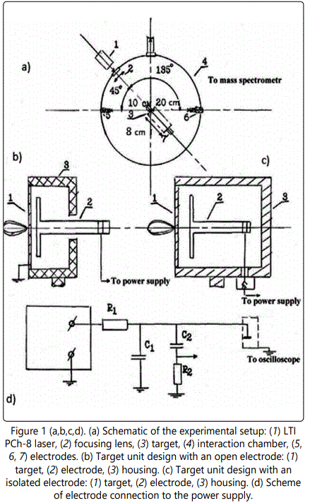
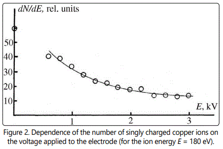
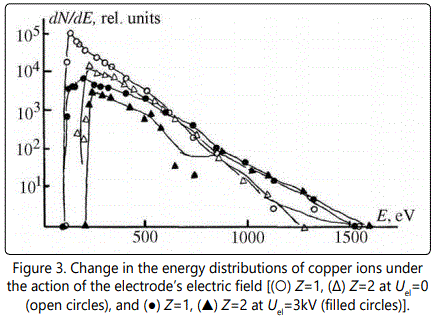
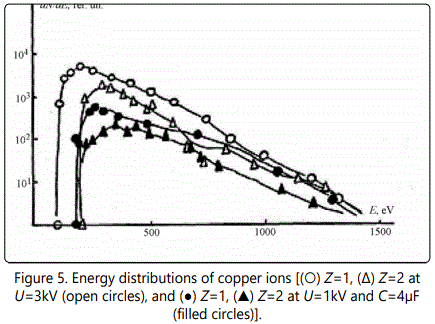
The experimental setup is shown schematically in Figure 1a. The main elements are an LTI PCh-8 laser, a chamber of interaction of radiation with matter and a time of-flight mass spectrometer with a magnetic analyzer. Laser light in the interaction camber was focused on a target made of copper, molybdenum, and carbon. Electrodes, to which a voltage from the power supply was applied (Figure 1b), were located at different distances from the plasma torch formation and at different angles to the plane of the sample. The targets were in the center of the chamber and rotated so that the point of the plasma formation did not change its position with respect to measuring devices and the electrodes. Figure 2 shows the dependence of the number of singly charges copper ions on the voltage applied to the electrode [electrode (7) in Figure 1a] at an ion energy of 180 eV. Upon reaching the voltage of 600V the number of ions in the beam is significantly reduced, and at a voltage of 2.5 kV the number of ions emitted in the direction of the analyzer is five times less than initially. When considering the impact of the field of the electrode with the 3-kV voltage applied (Figure 3), it is found that the overall structure of the energy distribution remains the same, but the number of particles in the left low-energy part of the spectrum decreases.
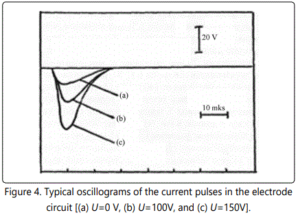
In addition, the effect of the electrode’s electric field on the laser plasma is accompanied by the flow of the current in the electrode shown in Figure 1b. Typical oscillograms of such pulses are shown in Figure 4. An increase in the voltage applied to the electrode was accompanied by an increase in the current; at the same, the effect on the plasma also increased. The effect on the plasma was observed only in the case of a positively charged electrode. When the electrode potential was negative, there was no current in the circuit and the effect of the field on the characteristics of the laser plasma was absent. An important factor that significantly affects the products resulting from the laser plasma expansion is the value of the current of the storage capacitor in the circuit of the electrode. Thus, the inclusion of an additional storage-capacitor electrode into the power supply circuit leads to a significant increase in the field effect, while reducing the voltage on the electrode (Figure 5). Thus, it should be noted that the appearance of the effect of the electrode’s electric field on the plasmoids is due to the contact of the electrode with the plasma and the value of current flowing in the circuit (in the case of the electrode screening its effect on the plasma was absent).
Electrode position in a plasma influence
An important parameter that significantly affects the degree of the effect of the electrode field on the plasma is the position of the electrode in relation to the point of the plasma torch formation. Figure 3.1a shows the general arrangement of the electrodes. Two electrodes are located behind the plane of the sample. The distance from the point of the plasma torch formation to the electrodes is 8, 10, and 20cm. The tilt angles relative to the normal to the sample surface are 45, 155, and 180°.
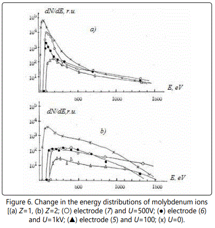
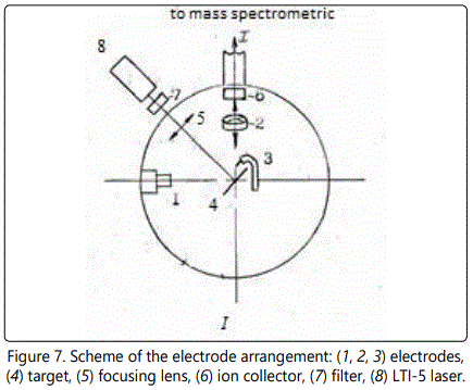
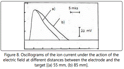
As follows from the spectra in Figure 6, the greatest effect on the plasma was exerted by the electrode that is closer to the point of the plasma torch formation. In this case, the greatest effect was achieved at the electrode (5) for a voltage that is 10 times smaller than at the electrode (7). Besides, the shape of the electrodes also changed. The influence of the electrode position on the plasma expansion products was studied using a steel electrode in the form of a ring (2) with an outer diameter of 30mm and an internal diameter of 26mm, and thickness of 6mm (Figure 7). The electrode was moved along the 1-1 axis, and the distance between the electrode and the sample varied from 140 to 55mm. In the vicinity of the point of the plasma formation, it was impossible to mount a ring electrode, and so use was made of the electrode (3), which represents a segment of an 8-mm-long RK-50 cable with a diameter of 0.5mm. The electrode was placed at a distance of 8mm from the point of the plasma formation torch along the 1-1 axis and 10mm lower. Figure 8 shows the oscillograms of the ion signal obtained from a collector installed at a distance of 14cm from the sample on the 1-1 axis. The first grid before the collector is grounded, and a voltage of 100V is applied to the second grid. The oscillograms of the ion signals were recorded for two positions of the ring electrode [(a) 55 mm, and (b) 85mm]. The radiation flux density in these experiments was 109W/cm2, and the sample was made of molybdenum. The potential on the ring electrode was +50V. The comparison of the oscillograms indicates that the number of ions in a beam with an energy of 200eV decreases when the electrode is moved to the point of plasma formation.
Effect of the potential value on the ion characteristics
First, it is convenient to consider the effect of the potential on the plasma expansion products at the ring electrode, registered in a distance of 362cm (Figure 9). For singly charged ions at a voltage of 15 the energy distribution narrows down both on the left and the right (wings) with a simultaneous decrease in the number of particles in the distribution maximum. A subsequent increase in the potential affects only the reduction in the intensity maximum without changing the ‘wings’ of the distribution.
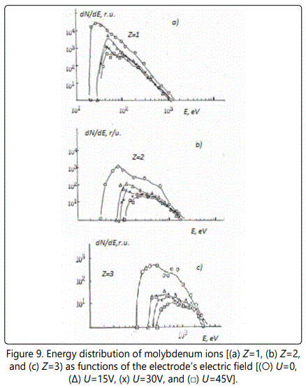
For two- and triply charged ions at a +15 V voltage applied to the electrode, there is a shift to higher energies of the left low-energy boundary of the spectrum and the number of particles in the intensity maximum decreases. It should be noted that within the measurement accuracy the electrode position (10 and 14 cm from the interaction point) had no effect on the dynamics of the spectra in the range of voltages up to 45 V.
Consider the oscillograms of the ion and electron current, obtained from the collector (Figure 11), which was at a distance of 140 mm from the point of the plasma torch formation. The distance from the point of the plasma formation to the electrodes was 85mm and the distance from the electrode to the collector was 55 mm. The radiation flux density on the sample was equal to 2×10⁹W/cm2. As the voltage at the electrode was increased, the collector measured a decrease in the number of ions in the region of low energies, in agreement with the data on changes in the energy distributions obtained by the mass-spectrometric technique. When applying a positive potential of +100 V to the second grid, an electron signal was observed at the collector at U=0. With increasing potential on the electrode, the electrons gradually disappear from the plasma and the ions, which overcome the energy barrier of 100 V, are registered. The electron signal (Figure 11b) in this case is identical to the ion signals observed (Figure 11a) at a potential of −100 V on the second grid of the collector.
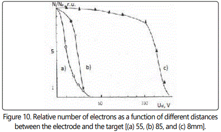
Figure 10 shows the changes in the quantitative characteristics of the electrons as a function of voltage applied to the different shape electrodes located at different places of the chamber. Curve
(a) in Figure 10 shows the dependence of the number of electrons in the plasmoid on the potential
applied to the electrode (3). On approaching the point of the plasma torch formation, it is needed to raise the voltage on the electrode, in order to obtain a significant change in the number of electrons in the plasma.
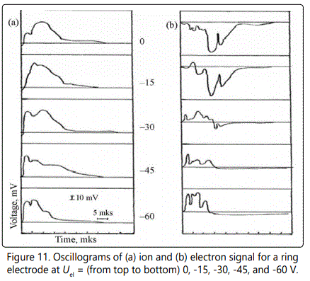
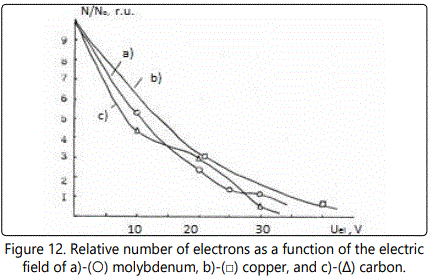
Figure 12 shows the changes in the quantitative characteristics of the electrons in the plasma for different target materials, obtained by the collector. The electrode (2) is located at a distance of 85mm from the target, and the radiation flux density on the target is 2×10⁹W/cm2. One can see from the figure that the dependence of the number of electrons in the plasma on the potential at the electrode does not change with the atomic mass of the ions. When it comes to the mass spectrometric analysis of the laser plasma, at large distances from the point of the plasma torch formation and the electrode it can be noted that the deformation of the energy distribution functions of molybdenum ions is more significant compared to the deformations of the distribution functions of copper ions (comparison is conducted for the case when the electrode is behind the surface of the sample).
The electrode in the plasma influence on the plasma torch characteristics
It was shown above that when a positive potential is applied to the electrode, which can be located in different parts of the vacuum chamber, we can observe the effect of some potential on the characteristics of products of laser plasma expansion. It was found that the effect is observed only when the electrode is immersed in the plasma (the electrode can be located behind the bulk sample). Only when the electrodes are completely isolated from the plasma, no effects are observed. Let us analyze the oscillograms of the currents that flow in the circuit of the electrode. The electric circuit of connection of the electrode to the power source is shown in Figure 1d. The current amplitude increases with increasing voltage on the electrode. The pulses appear with a delay with respect to the time of exposure to laser radiation and plasma torch formation. The value of the time delay is 7 µs for the case when the electrode is at a distance of 10cm for the copper sample. The current maximum corresponds to 27±3µs and drops to the level of 0.1 during 150±10 µs. The delay time decreases and is 5µs for the electrode located at a smaller distance (5 cm) from the sample (molybdenum). The time of the current maximum corresponds to 11±3 µs and falls during 33±5 µs.
It follows from the current characteristics that the temporal structure of the current pulse and the amplitude depend on the rate of the plasmoid expansion, the number of particles in the plasmoid, and the velocity distribution. These laser plasma parameters are determined by the radiation flux density on the sample, the atomic composition of the sample and the geometrical arrangement of the electrode.
It was found in the experiments that the electrode placed in the laser plasma focus not only takes measurements, but also affects the laser plasma expansion products: a sharp decrease in the number of ions of all charges is observed, there is a shift to higher energies of the low-energy boundary of the spectra of all the ions present in the laser plasma, and collector measurements reduce the number of electrons in laser plasma. The effect of the electric field of the electrode placed in the plasma, apparently, can be attributed to the case when the processes occurring near the Langmuir probe placed in the plasma are considered. It is only necessary to note that such an electrode in plasma perturbs the plasmoid.
To enhance the effect of the electrode’s field on the plasmoid, a storage capacitor with C=4µF is installed in the electrode circuit. Evaluation of the electric charge stored in the capacitor (when the capacitor voltage is 100V) is equal to Q = 4×10⁻⁴C, which corresponds to the number of charges, 6×10¹⁵. In the laser plasma 1015–1016 electrons are formed at a flux density of 1010W/cm2. These estimates allow us to understand why, in order to obtain a comparable effect on the plasmoid, it is needed to increase (by a on order of magnitude) the voltage on the electrode with decreasing capacitance by an order of magnitude. Based on the experimental results it can be assumed that as soon as the electrode is immersed in the plasmoid, there will be an outflow of electrons from the laser plasma; this process will be terminated by the emerging field of positively charged ions. In this case, the quasi-neutrality of the plasmoid may be violated. The resulting uncompensated ion charge leads to a decrease in the ion beam intensity. Another possible mechanism involves the processes in the plasmoid affected by the electrode’s field. At a field strength in the plasma, 10– 100V/cm, there appears the regime of ‘runaway’ of electrons [2], which leads to the formation of an unstable electron beam with a large increment. The conditions are created for the growth of small initial perturbations and the development of turbulence. In the case of a plasma with a current, the determining factor is the development of ion-acoustic oscillations. Thus, the experimental results may be due to the growing turbulence in a laser plasmoid with a current.
Effect of a transverse magnetic field on the formation of the laser plasma focus
The behavior of the laser plasma from the moment of its formation and in the initial period of formation and expansion in the transverse magnetic field [3] is both of physical interest, which makes it possible to understand more fully the processes occurring in the plasmoid in the early stages of formation, and of technical interest for application of beam particles in accelerators.
Region of the field- plasma interaction
The setup used in the experiments (Figure 13) consisted of a laser with a focusing system; a vacuum chamber; an electromagnet producing a magnetic field, which is transverse to the direction of the laser plasma expansion; and a time-offlight mass spectrometer with a magnetic energy and mass analyzer and detection of ions by the secondary electron multiplier (SEM). The Nd:glass laser produced a power density in the range from 2×10⁹–2×10¹¹W/cm2. The vacuum chamber with a target inside (as a target material use was made of tungsten and molybdenum) was placed between the poles of the electromagnet and made of a copper waveguide segment (cross section of 3×1cm2), which guaranteed the penetration of the magnetic field in the vacuum volume. Besides, the target could be moved along the axis of the chamber, thereby making it possible to study the effect of the magnetic field to form a laser plasma inside or outside the region occupied by the magnetic field with the value in the range from 0 to 10kE. The transverse (to the direction of the plasma expansion and to the magnetic field lines), size of the region occupied by the field e3xceeded the size of the chamber; in this case, the change in the field could in this direction be virtually neglected. The longitudinal size was about 3cm, i.e., it was approximately equal to that of the chamber, and, consequently, to the transverse size of the zone of the magnetic field – plasma interaction.
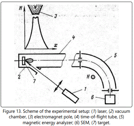
Effect of a transverse field on the ionic component
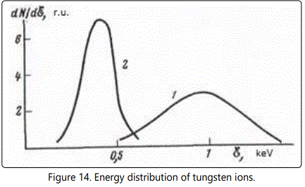
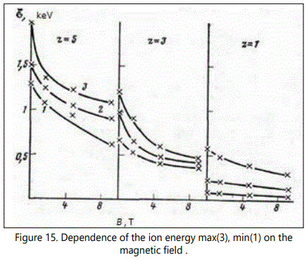
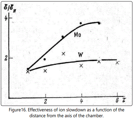
With the laser plasma flying through the region occupied by a transverse magnetic field, the ion energy decreases. Thus, if the freely expanding laser plasma contains tungsten ions with a charge from 1 to 6 (1010W/cm2), the energies of which reach 2.2keV, then at a field of 10kE, the charge and the number of ions remain the same within the limits of experimental error, and the ion energies decreased by about half to 1.2keV (Figure 3.14); lighter ions (molybdenum) are slowed down more effectively. Thus, the ratio of the average energy in the palsmoid at 0 and 10kE reached 2.3. The most significant effect is exerted by the magnetic field on the expansion of ions with a maximum charge.
The size of the plasma region exposed to the field was changed by shifting the electromagnet along the vacuum chamber. These experiments showed that the energy shift increases with increasing interaction region of the field and the plasma. Changes in the direction of the magnetic induction vector in the transverse plane are not affected by these effects.
Apparently, the effect of the laser plasma slowdown in a transverse magnetic field can be qualitatively described as follows. When the plasma flies into a magnetic field, the electrons are subjected to the Lorentz force, which leads to the bending of their trajectories; this results in a transverse velocity component and in a decrease in a perpendicular velocity component of the electron motion to the sample surface, which will automatically reduce the ion velocity. But this mechanism will only work in a small, dense region of interaction where there occur the processes of acceleration of ions with electrons. It is possible that the action of the Lorentz force on the electrons leads to the emergence of the electron current in a direction perpendicular to the motion of the plasmoid and the magnetic field lines. The current flows in the plasma and is short-circuited by the conducting walls of the chamber.
The model problem of the plasma incoming into the magnetic field is presented in papers [4,5]. Here we neglect the angular expansion of the plasma, and we assume that it moves in the direction of the X axis, and the magnetic field is directed along the axis Y.
Using simple calculations presented in work [3], it is easy to obtain the estimate:

The estimate agrees well with the experimental data, and the formula qualitatively explains the fundamental features. For the quantities in (3.1), we used Z=2, 104E, V0=3X106cm/s, M~4×10-22g, G=1013Ohm-1, ne=1016cm-3 (q=1010W/cm2, the diameter of the focusing spot is 300µm). From (1) it follows that the efficiency of the plasmoid slowdown should increase sharply with increasing magnetic field strength and, in addition, it should be enhanced by reducing the electrical resistance during the heating of the electrons due to the Joule heating.

The transverse magnetic field can slow expansion of the laser plasma, the most effective slowdown being observed for the high-energy part of the plasmoid containing multiply charged ions, which is a good feature when using the laser plasma as a source of multiply charged ions for accelerators.
Laser plasma in a plasma focus
In plasma physics, use is widely made of pulsed plasma accelerators, where the plasma is formed by the breakdown of the interelectrode gap which is filled by a gas in a stationary or pulsed manner and accelerated by electrodynamic forces. At certain parameters the plasma sheath can collapse on the axis in front of the injector, forming a so-called ‘plasma focus’ (PF). The PF is a source of high-energy particle fluxes (up to several MeV), X-rays and neutron radiation.
Since the laser plasma is a source of particles of any elements, in particular containing hydrogen and deuterium, this (using the PF design) makes it possible to design a setup for additional heating and ionization of the laser plasma [6].
Such a method of producing the plasma in the PF injector, compared to the conventional technique, has some advantages:
(i) Control of the parameters of the plasma sheath: length, density, target material. You can change the shape, composition and number of particles in the sheath at the stage of the plasma formation.
(ii) Symmetry in space with a controlled degree of ionization.
(iii) Reduction of the current losses beyond the accelerated sheath.
(iv) Increase in the speed of the sheath motion before the collapse.
Figure 17 shows schematically a setup for studying the processes in the laser plasma focus. The beam of a pulsed CO2 laser (10) focused by the lens system is directed into the ring target (1) and causes the release of a plasmoid consisting of the target materials (in the experiments use is made of the materials containing isotopes of hydrogen, which are impregnated in a variety of metals) into the interelectrode gap in the axial direction.
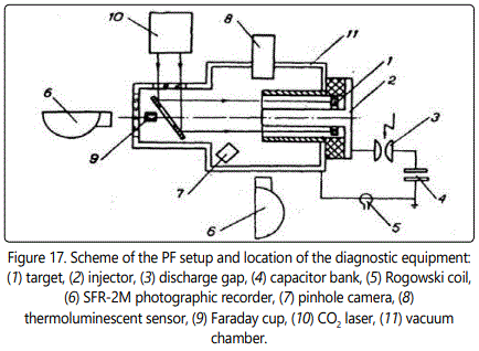
Changes in the characteristics of the laser radiation and target make it possible to change the parameters of the plasma formed. The synchronization system, after a certain time delay, starts controlled discharge gap (3), short-circuiting the plates of the capacitor bank (4) to the PF electrodes of Meiser type. The current flows along the plasmoid and the thus produced magnetic field accelerates the plasmoid, usually called the plasma sheath, which, after reaching the end of the inner electrode, is compressed by the magnetic field, and from which a plasmoid is formed from a dense hot plasma – ‘plasma focus’.
A peculiarity of the laser focus (LF) is the possibility of varying the parameters of the current sheath and its significant acceleration in the process of movement and collapse, as well as the increase in the efficiency of waist compression, in the absence of a gas medium.
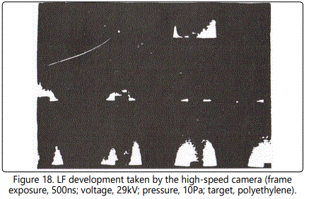
The research conducted allowed one to carry out operation modes, leading to the formation of pinch structures. Figure 18 shows a typical high-speed camera photograph. Measurements performed by using X-pinhole cameras, led to the observation of X-ray sources with the characteristic region of 100µm in size and energy of 1keV. Using thermoluminescent sensors the energy spectrum of the radiation was recovered, which in the range 1–20keV was close to the spectrum of the plasma bremsstrahlung. Probe measurements showed that the laser plasma focus is the source of ions with very high energies.
Let us consider now the motion of the plasma sheath under simplified LF conditions when tracking is absent.
We obtain in the first nonzero approximation:

Thus, the law of the waist compression is characterized by the fourth degree of time and not the second, as in the case of the classical Z-pinch. In order to optimize the rate of energy input to the discharge, we ill change the parameters of the electrical circuit. The equation of the circuit has the form:

where L0 is the external inductance, and L1 the discharge inductance.
For effective discharge development temporal coincidence of the current maximum flowing through the discharge is important (for the time of maximum compression). The problem is to match the discharge time to the dynamics of motion of the current shell. Since the initial velocity of the shell is large enough V0=106–107cm/s, and the initial conductivity is high (Q=Te1.5), then the use of the usual parameters (C=1–10µF, L=0.1–1µG) is ineffective: the shell accelerates and collapses long before the current reaches a maximum, and so it is necessary to reduce the discharge time Tdis=L00.5/V0 at the same energy, by reducing the inductance and increasing the voltage across the discharge gap. This can also lead to an increase in the rate of the current rise:

The maximum achievable current is determined by:

On the other hand, the achievement of Imax requires the fulfillment of the ratio L0=L1. When L0>L1, too much power remains in the external circuit, and when L0<L1, too much energy is spent to accelerate the shell in the initial phase. Therefore, for the successful implementation of the LF idea, it is necessary to use sources with a fast energy input (such as Blumlein lines). This approach is implemented using a new original design [7] whose diagram is shown in Figure 19. It allows one to reduce to a minimum all parasitic inductances and ensures a minimum time of the energy input into the discharge, which is equal to (2–5)×10-8 s. With a small energy input E0=0.1 J, the current up to 5 kA is provided. The results of experiments with this system are shown in Figure 20.
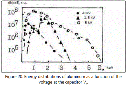
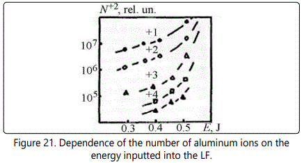
Changes in the energy distribution of multiply charged ions with increasing voltage across the discharge gap from U0=0 and U=5keV (aluminum anode, discharge gap d=5mm, C=0.01µF, angle 0° with respect to the device axis) testify about the increasing compression efficiency of the laser plasma by the magnetic field of the increasing discharge current. Figure 21 shows that this is accompanied by a sharp (almost 2 orders of magnitude) increase in the number of ions of the corresponding charge and in Z to 6 with increasing initial electric field up to E=1kV/cm.
Thus, the results obtained with the use of LF heating (LF-pinching) offer promising new opportunities not only for sources of multiply charged ions, but also for the study of processes in such plasma.
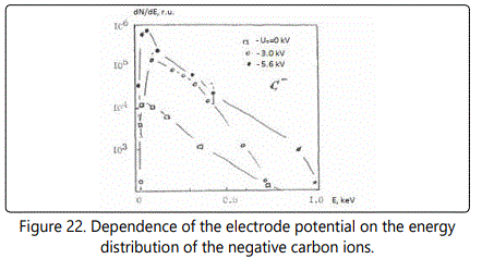
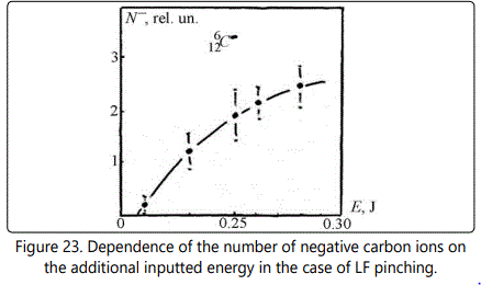
Apart from highly charged positive ions, LF expansion is accompanied by the formation of negative ions. The results of the mass spectrometry analysis of negative ions (anode material is graphite) are presented in Figure 22. The energy distribution of the negative carbon ions in the laser plasma (without the effect of the electric field) has a maximum at 15eV ion energy (2×10⁹W/cm2) and energy spread of 0.5keV. With increasing electric potential on the electrode system to V=5.6kV the maximum of the energy distribution shifts out in the energy range 50– 100eV when the distribution amplitude grows by about 2 orders of magnitude. The number of negative carbon ions increased by 10 times with increasing energy input in the discharge up to 0.3J (Figure 23). Increasing the yield of negative ions can be attributed to the fact that there was an increase in the number of positively charged ions (Figure 21), and, therefore, an increase in the number of recombination neutral atoms. This recombination leads to an increase in negative ions.
The use of this type of LF heating [7] can greatly increase the possibility of laser-plasma medium as a source of positive and negative ions.
Further experiments on the use of the PF to heat the plasma were carried out on a modernized setup, which makes use of an injector made of cylindrical electrodes with diameters of 15 and 50 mm, length of 150 mm (the electrodes have inserts made of copper, graphite, polyethylene, acrylic glass, porcelain and other materials). As a radiation generator use is made of a pulsed CO2 laser with a double transverse discharge. When employing an unstable resonator, an annular laser beam was directed to the target through the optical elements such as axicon, or through lenses located along a circle. The number of ions formed in the injector varied from 1014 to 1017. In the experiments use was also made of additional diagnostic facilities (Figure 17): Rogowski loop, high-speed photo camera SFR-214, X-ray pinhole cameras, thermoluminescent detectors, grid probes and time-of-flight mass spectrometer. 109
The current oscillograms with the Rogowski loop made it possible to calculate a period of 5µs and an amplitude of up to 100kA for the discharge current injector. For targets of light elements (e.g., polyethylene) with a symmetric output of plasma to the end of the electrode system, on the anode we observed a spot of diameter 5 mm and length 20mm. The lifetime was equal to 3–4µs (Figure 18).
The analysis of the results obtained and the qualitative peculiarities of the laser plasma pinching indicate the need to take the advantage of the ‘fast’ (10-7s) energy input into the discharge (Figure 24). The dynamics of the formation of the charge and energy distribution of the output ion beam at a higher energy input and the electric field up to 103V/cm is determined by an increase in the compression efficiency of the laser plasma by the magnetic field of the increasing discharge current. The specific shape of the spectra of multicharged ions, to a certain extent, correlates with the spectra obtained in experiments with laser plasma at high laser intensities, which opens up new possibilities in the study of fundamental processes in laser plasma itself.
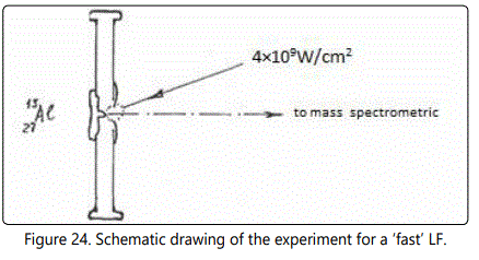
In the experiments on the LF formation the electron fluxes were investigated at the setup consisting of the electrode system; the discharge chamber; and the IK-25-12 storage capacitor, which is vacuum-packed to the discharge chamber to minimize the circuit inductance (Figure 24).
This made it possible to carry out the process of pinching in the first quarter of the discharge period
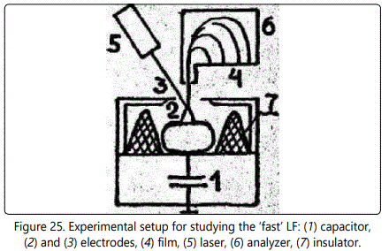
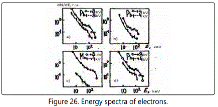
Figure 26 shows the energy spectra obtained for inserts made of molybdenum and lead; these spectra make it possible to trace the effect of the changing polarity on the energy characteristics of electrons. The traditional choice of polarity, when the central electrode is the anode, is characterized by an increase in the total number of high-energy electrons and the appearance of some features in the spectra at electron energies of 100keV. The presence of this feature is apparently due to the onset of an intense electron beam during micro-pinching of the discharge plasma. Therefore, we can assume that at this polarity compression is more effective. Reduction in the total number of registered electrons in the case of reverse polarity is explained by the spread of the electron beam during its expansion in front of the entrance slit of the analyzer. Also of interest is the dependence of the electron flux on the storage capacitor voltage (Figures 26c, d). The discharge current varies from 50 to 100 kA with changing the voltage; in this case, the compression is readily achieved, as evidenced by the change in the shape of the energy distribution of electrons. One can see that no compression is observed for refractory molybdenum at an initiating laser energy of 0.1 J and a voltage of 4 kV due to the lack of seed laser plasma. When the voltage is further increased up to 8 kV, secondary processes after the breakdown of the discharge gap provide enough carriers for the regime, while the low-melting lead this regime already takes place at a voltage of 4 kV, which corresponds to the discharge current of 50 kA.
The results of the study of the X-ray polarization [8]. point not to the axial but the transverse (with respect to the discharge axis) motion of fast electrons in the micropinch. This should be expected because the Larmor radius of electrons with energies of 10–100keV is much less than the micropinch radius observed in the experiments [6]. Consequently, the electrons can move mainly along helical trajectories along magnetic field lines, moving in the longitudinal direction due to the drift in an inhomogeneous field. It is easily seen that the electrons outside the pinch will drift in the direction which is opposite to that of the current. Within the pinch the centrifugal drift is also directed against the current, and the diamagnetic drift – along the current. In our case, at a current of 105A and a microprinch radius of 10-3cm, the drift velocity of electrons with energies of 10–100 keV at the plasma boundary is of the order of 108 cm/s, i.e., the time of micropinch ‘acceleration’ in the plasma will be10-10 s, which is obviously less than the lifetime of the micropinch itself [9]. Only a small fraction of the relativistic velocity electrons trapped in the axial region, for example, as a result of a drift in crossed electric E and magnetic B fields can rapidly, i.e., a rate determined by their kinetic energy, leave the discharge plasma [10].
Magnetized electrons in the pinch discharge plasma can be accelerated under the influence of some other mechanisms. In compression of the pinch plasma the collisionless electrons retain their adiabatic invariant and torque. Reducing the pinch radius and a corresponding increase in the magnetic field will lead to an increase in the transverse and longitudinal energy of the electrons [10].
For example, during the second compression of the micropinch [11] when its radius varies from 10-2 to 10-4cm the energy of the electrons can increase by 102–104 times (compression time of 10-11s) and is much smaller than the characteristic time of electron collisions. This mechanism of electron acceleration can explain the anticipatory appearance of radiation with energies of 100keV, compared with the radiation of multiply charged ions of the highest multiplicities appearing in the micropinch plasma at the stage of maximum compression [12].
The above analysis of a fairly wide range of experimental data allows us to conclude that the development of acceleration processes in the plasma of a multicharge ion source apparently plays an essential role in the phenomenon of emission of multiply charged ions, thereby affecting the plasma dynamics in the pinching process. In addition it should be noted that the fast electrons, leaving the region of the micropinch formation interact with the relatively cold peripheral plasma, thereby increasing the total contribution to the ion emission.
Sources of neutral atoms for collective heavy-ion accelerators
The 1980-1990s saw a significant development of one of the collective methods – ion acceleration with electron rings [13].
This collective heavy-ion accelerator (CHIA) has a number of advantages over conventional accelerators, primarily due to the use of the electric eigenfield of the electron ring with a high intensity for ion acceleration. This ensures a significant gain in the rate of energy accumulation of particles, and hence the length and cost of collective accelerators is much less than that of conventional ones.
Ions are formed and stored in electronic rings of neutral atoms by electron impact ionization. By storing the ions inside the ring for a long time, on can obtain the ion beams of high intensity and degree of ionization. In addition, a collective accelerator is universal with respect to the type of accelerated ions. Such an accelerator makes it possible to obtain the ion beams with the elements throughout the periodic table and the high intensity of heavy elements up to uranium.
Requirements to pulsed atom sources
To accelerate ions in a CHIA requires certain parameters of electron-ion rings. The number of electrons in the ring should be 5×10¹³; otherwise, the strength of the electric eigenfield of the electrons will be insufficient for acceleration. On the other hand, the adgesator (an adiabatic generator of atoms) of the CHIA allows forming a ring with the number of electrons Ne=1.5×10¹³ [14]. The ions from a selected element should be accumulated from a pulsed flux of atoms crossing the electronic ring at the compression stage. This type of loading allows one to adjust the number of ions trapped by the ring and the loading time (in other words, the ion charge). For a pulse loading of the ring by ions, the initial flux of neutral particles must meet the following requirements:
(i) The flux of atoms should be formed geometrically so that the maximum number of particles would cross the volume of the electron ring.
(ii) The interaction time (duration) of the atom flux with the electron ring should be optimal, i.e.,
longer than the characteristic time of ionization of neutral atoms (8×10⁻⁶s for lead). The lower boundary is limited, apparently, by the design capabilities. The most optimal time is no more than a few tens of microseconds. The flow rate of neutral particles is selected as follows.
If the characteristic time of ionization of a neutral atom is much less than the time of flight through the ring, the jet is almost completely ionized at distances smaller than the smallest size of the ring, and a part of the electrons in the ring is not involved in the ionization process. In this case, increasing the jet velocity, we can increase the number of ions in the ring by making fuller use of its ionizing capacity. When tr<<to, a change in jet velocity does not affect the number of atoms in the ring. The actual value of the velocity of neutral atoms should be 104–105cm/s.
(iii) The average number density of neutral particles in the jet must be such that, under the existing values of the duration t0 and the specific geometry of the jet, to provide the required number of Ni ions in the ring. The value Na
atoms of different elements injected into the ring depend on the parameters of the electron rings in the accelerator and should be in the range from 109–1011cm-3.
(iv) The relative instability of the basic parameters of the pulsed fluxes of the atoms must be better than 5%. It should be noted that when the CHIA is used as a heavy ion accelerator injector [15] it is needed to have the relative stability no worse than 1%.
In addition to these requirements, the design of the sources must meet the following conditions:
1. atom fluxes generated should virtually overlap all the elements of the periodic table;
2. the source should be characterized by vacuum cleanness as it works under conditions of deep (10-7–10-6Pa) vacuum of the adgesator chamber;
3. the source should operate in a magnetic field (up to
2 T) and not to distort the generated magnetic field;
4. switching frequency of the source must be in the range 20–50Hz;
5. the source should have the life time of >106 operations;
6. the laser atomic source should be universal;
In the range of radiation flux densities 107 -5×10⁹W/cm2, for a wide range of target materials the number of neutral atoms is greater than 95% of the total number of particles.
For lead, at a distance of 10cm from the plasma formation and a flux density of 4×10⁸W/cm2 , the concentration of atoms is equal to 4×1011cm-3. The information obtained in our experiments on the atomic velocity distribution makes it possible to determine the flux duration at any distance from the target. Since the duration of the clusters of neutral atoms as a function of the flux density of the laser radiation and the target material at a distance of 10cm is 10–50µs, and the energy of the directional movement lies in the range from 1 to 1000eV, the velocities of the atoms are in the range 105–106cm/s.
Source design and the loading scheme of atoms
The characteristics of neutrals of plasmoids studied in detail made it possible to create the working versions of a laser source of atoms and the schemes of injection of such fluxes in the electron ring [16-20].
A laser source of atoms consists of a laser, a focusing lens and a target, on the surface of which laser radiation is focused. The target was made of a substance whose atoms it was necessary to obtain. The focusing lens and the target were placed in a vacuum chamber of the adgesator, and the laser was outside the chamber (radiation is coupled into the chamber through a window). The simplicity of the source design allowed one to position the target in the proximity to the region occupied by the electron ring, and thus, to effectively use the fluxes of atoms from the target.
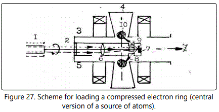
One of the ways to load the ring (central source version) is shown in Figure 27. The laser (1), whose radiation (2) passes through the window (3), enters the adgesator chamber (4) and tube (5) (supporting structure) and is focused by the lens (6) on the target surface (7). The flux of atoms (8) through the holes in the collimating tube (9) propagates into the compressed electronic ring (10). In this arrangement, the flux of atoms should be directed at an angle of 45° to the Z axis. The azimuthal flux uniformity requirements and the possibility to inject atoms into the electronic ring at different moments of its compression (at different radii from 3.5 to 12cm) are achieved by delaying the flux of the atoms relative to the electron beam. The distance from the target to the compressed electron ring of radius 4cm is no more than 6cm, which allows one to load fairly dense fluxes stream of atoms.
The size of the partitions between the three collimating holes of the cylindrical surface of the tube (of diameter 20mm and wall thickness 0.5mm) is small (about 2mm), which provides good azimuthal uniformity of the ring loading. The angular distribution of the ions has the form of ‘lobes’ with the axis which coincides with the normal to the target, the higher charge ions having a narrower ‘lobe’. When the power density is 107–109W/cm2, one can observe in the plasmoid the ions with a charge of no more than +1, occupying an opening angle of no more than 45° from the normal. Thus, the tube of the source mostly screens the region of the compressed ring from laser plasma ions. The longitudinal magnetic field of the adgesator increases such a screening due to the ‘narrowing’ of the angular distribution of the ions.
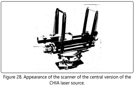
The laser, as the outer part of the source, can be quickly replaced in the case malfunctioning (its life span included 106 operations). The element generally specifying the source parameter is the sample whose surface is subjected to erosion in the interaction with the laser light. The target is placed in the adgesator chamber; quick change of the sample for the central source version is almost impossible, because of the depressurization of the chamber. In such conditions, the maintenance of the stability of the atom flux parameters, i.e., adequate resourcing of the target can be achieved by changing the interaction point. In the laser source of atoms (central version) the interaction point changes by scanning the laser beam over the surface of a stationary target. Laser radiation is scanned by a special device providing a plane-parallel rotational movement of the laser around the Z axis, which is shown in the photo in Figure 28. Thus, the radiation falls onto the focusing lens at the points on the circle. The target lifetime increases with the size of the interaction spot. Changing the position of the interaction point on the sample within a few mm does not lead to a significant change of the atom flux parameters in the region of the compressed electron ring, because the angle between the normal and the axis, which is directed from the interaction point to the ring, as well as the distance between the interaction point of the ring change only slightly.
The scanning device is made on the basis of the optical table with the main and the alignment lasers, the system of plane-parallel motion of lasers driven by two RD-09 electric motors, providing the speed of 2.5rev/min. The rate of rotation and deviation of the radiation axis from the Z axis of the chamber can be controlled remotely.
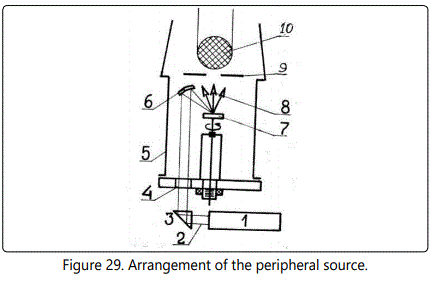
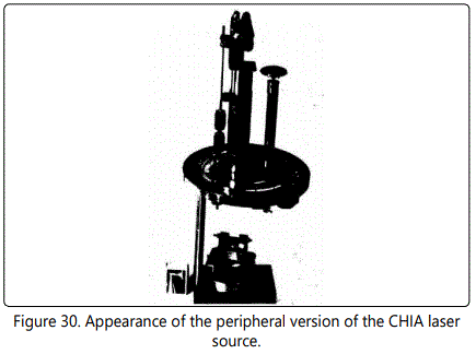
To study the accumulation processes in the electron rings, it is needed to provide a pulsed flux of atoms into a ring of large radius (30 to 35cm). To implement such an operation mode, the second (peripheral) version of the laser source was designed. In this case the source is located in the lower vertical sleeve of the adgesator chamber. Radiation (2) from the laser (1) (Figure 29) is incident onto the total internal reflection prism (3), vertically passes through the cell window (4) of the adgesator chamber (5), and falls onto the spherical mirror (6), which focuses the radiation on the surface of the target (7). The atom flux (8) through the collimating aperture (9) enters the electronic ring (10). In this source the stability of the atom flux parameters and the necessary lifetime of the target are provided by changing the interaction point due to the sample rotation and the tilt of the spherical mirror. The target rotation is performed by by a magnetic drive: AC magnetic field of the DSDR 1-2 motor penetrates through a thin-walled tube, which houses a rotor mounted on the axis of the target rotation. Figure 30 shows the appearance of the peripheral version of the laser source. A distinctive feature of this version is the fact that laser radiation falls onto the target at an angle of 40° to the normal. The magnetic field of the adgesator for fluxes of atoms is in this case transverse and should not significantly affect the characteristics of the flux of neutral particles. The magnetic field of the adgesator in the vacuum chamber of the bench was provided by a magnetic coil with the parameters: the average diameter, 6 cm; and the number of coils, 4×4=16. The current pulse in the form of a sine halfwave with duration of about 200µs and amplitude up to 10kA passed through the coil. The induction in the center of the coil in the air reached 3 T. Syncronization system provided the interaction of laser radiation with the target at the time corresponding to the maximum value of the field. The geometry of the target position with respect to the coil should lead to a change in the magnetic field; therefore, the target was mounted at a distance of 5 mm from the end of the coil. The real value of the magnetic field was at least 0.3T, which is sufficient to explain the effect of the magnetic field on the flux of the atoms. It was found that (i) the longitudinal magnetic field does not reduce the yield of neutral atoms from a laser plasma, and (ii) some increase in the number of atoms coming from the target along the normal is, apparently, due to the enhancement of the recombination processes.
In the laser source of atoms (in the adgasator chamber), when the flux of the particles comes from the target at an angle of 45° to its normal, there is a decrease in the number of ions.
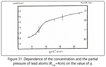
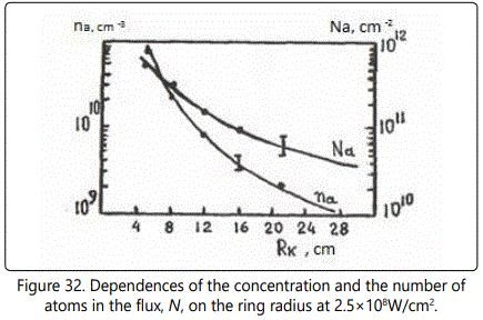
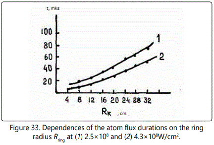
Figure 31 shows the dependences of the average concentrations and partial pressure in the flux of the lead atoms loaded into the ring with a radius of 4cm on the radiation flux density (the measurement error is 20%). Changes in the concentration and flux density of lead atoms for different radii of the ring are shown in Figure 32. Figure 33 presents the dependences of the atom flux duration on the ring radii at different flux densities. It should be noted that the atomic flux parameters satisfy the requirements for loading rings with ions, obtained in the calculations and listed at the beginning of this section.
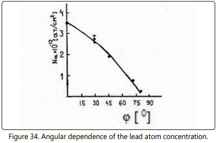
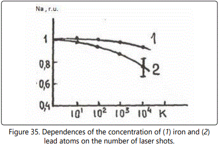
The experimental results showed that the tungsten samples have a very long life span, whereas the shortest life span (among the listed materials) is observed in indium targets. For other materials, we found a strong dependence of the target life span the on the size of the focal spot, which can be explained by a change in the number of atoms and retention of the atom flux duration in general. Figure 35 on the dependences of the concentration of iron and lead atoms (in relative units) on the number of laser shots. A similar dependence was obtained for lead and carbon atoms (108 W/cm2). Under these conditions, the concentration of lead atoms will decrease by 10% when the same point of the target is exposed to no less than 104 laser pulses. Changing the interaction point in the working versions of laser sources can provide a life span of at least 107 laser shots. The atoms are injected into the ring near (a few centimeters) the stainless steel walls of the adgesator accelerator; therefore, a part of the flux of atoms can be reflected from the wall and fall into the ring. In addition, a local region with a high concentration of the working medium atoms can be formed, especially at high repetition rates of the source (50Hz). A relatively small reflection coefficient, a sharp drop in concentration with distance, and the accounting for the angular dependence of the concentration of the reflected atoms lead to the conclusion about their limited impact on the accumulation of ions in the electron ring. Indeed, the concentration of lead atoms in the flux injected into the electron ring of radius 6 cm (the number of electrons is 1013) is equal to (5–10)×109cm-3. Given the above-mentioned factors, the concentration of the atoms reflected back into the ring does not exceed 5×108cm-3, i.e., less than 5% of the concentration of atoms in the main flux. High velocities of the reflected atoms, 7×105cm/s, cause a sufficiently small (of the order of hundreds of microseconds) time during
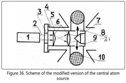
which the atoms non-ionized in the ring condense on the walls of the chamber. This time is much less than that (20µs) between the individual shots of the accelerator at a frequency of 50Hz. Thus, the laser source of atoms does not produce a noticeable background of secondary particles for subsequent operation of the collective accelerator, and the influence of the atoms reflected from the chamber walls is negligible in the current process of accumulation of ions. To inject atoms in the electron rings use can be made of modified loading schemes. One of these schemes is shown in Figure 36. The laser radiation (1) propagating parallel to the Z axis passes through the optical system (6), which consists of an axial cone (axicon) and a lens, and then is focused in the form of a ring on the surface of a cone-shaped target (7) with an opening angle up to 90°. The region of the plasma formation and the nozzle holes in the fore-chamber lie in the median plane of the adgesator chamber (4); therefore, the azimuthal uniform flux of atoms (8) from the laser plasma propagates along the compression axis of the electron ring (10). This version of the central source allows a ring of different radii to be loaded. The second version of the central location of the laser source is shown in Figure 37, which also has new design elements that allow for the injection of atoms at any radii of the adgesator into compressed electron rings. In this scheme, a reflector (4), made in the form of a cone with an opening angle of 90° and an axial throughhole, is placed between the lens and the target.
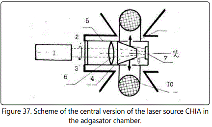
Nozzle holes are also located in the medial plane of the adgesator chamber between the reflector and the target. The cone can be made of glass or ceramic. It is intended primarily for the effective reflection of the flux of atoms and formation of directed beams. In addition, charged particle fluxes of laser plasma can be neutralized on the cone surface. Studies have shown that the reflection coefficient of the deposited layer of the material in question (the reflective surface is in the form of a plate made of stainless steel) amounts to 30%. The particles are scattered in this case almost isotropically. Selecting the appropriate shape of the surface and having properly arranged nozzle holes, one can load the electron rings at selected radii of the adgesator.
Laser sources of neutral particles in a collective accelerator
Experiments on loading an electron ring with ions by using a laser source were mainly carried out in a vacuum at 10-6–10-5Pa. It was found that the laser source operation in the adgesator chamber did not change significantly the vacuum in it. The first one – two hundred shots from the laser source source led to a decrease in vacuum down to 2×10⁻⁵. This process was associated, apparently, with the removal (during the first shots) of oxide films of the target material and gases adsorbed on the surface of the target. Thus, after the source installation and the depressurization of the chamber it is needed to periodically switch on the device in order to ‘clean’ the target surface. The source placed in the adgesator chamber had no effect on the pulsed magnetic field of the adgesator, i.e., the dynamics of the compression of the electron rings. This confirms the correctness of the choice of the source materials and design, sufficient accuracy in the nozzle tube adjustment. The relative stability of the radiation power (as well as its value over time) in real operating conditions in the accelerator could be efficiently monitored by the photodiode, the spread in these values not exceeding 5%.
A system of laser radiation alignment and a beam scanning mechanism used for scanning a target showed good results (after 3×10⁴ laser shots); the area of erosion represented a ring with the size, corresponding to the calculated one. After the first series of experiments on the Kuti-20 accelerator, the parameters of the working version of the source were tested on the bench. Measurements showed that the atom flux parameters did not change, with an accuracy up to 10%.
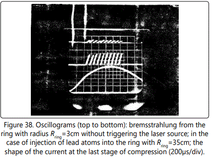
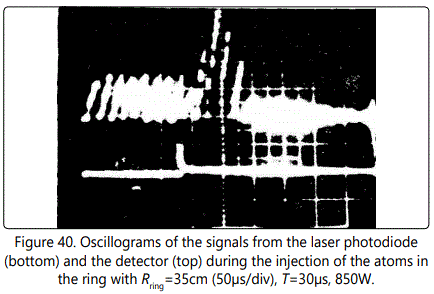
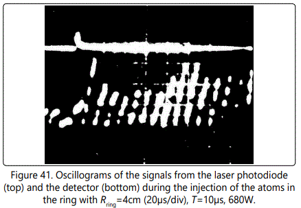
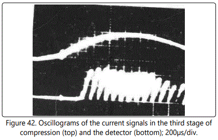
The experiments conducted allowed us to estimate the duration of the atom flux and the rate of its propagation by the bremsstrahlung of the electrons in the ring. Figure 3.40 shows the oscillogram of the bremsstrahlung during the injection of the atoms into the ring with Rring=35cm (in a constant magnetic field, without the ring compression). In this case, the depth of the potential well in the ring is not sufficient for trapping the ions, i.e., the duration of the electron bremsstrahlung corresponds to the time of their interaction with the injected atoms. It can be seen that the duration of the flux of atoms (80µs) is consistent with the data of Figure 33. At a distance of 35 cm a package of atoms ‘spreads’ due to the initial spread in their velocity. Figure 41 presents the oscillogram of the bremsstrahlung from the ring with a radius of about 3.5cm, which is injected into a flux of atoms. After an atom flux of duration 1015µs passes through the ring, which is in agreement with Figure 33, one can observe the signals of the electron bremsstrahlung on the accumulated ions. Using the delay (in Figures 40 and 41) between the laser photodiode signal and the bremsstrahlung signal, and taking into account the known target – ring distance, the velocity of lead atoms has been experimentally determined. The obtained values of the velocity well agree with those obtained by the methods described in previous chapters. Experiments on the loading of the rings with lead ions were held at an estimated number of electrons in the ring (5–7)×1012. The cross section of the atom flux by the median plane is a few centimeters in size (due to the relatively large size of the collimating holes in the tube), but the atom flux duration (a few tens of microseconds) is much less than the time of the ring compression (about 2.5µs). Therefore, taking into account the time of the flux propagation, it was possible to inject the atoms into the electron rings of a certain radius. Figure 42 shows the current oscillogram in the coil of the third compression stage and the oscillogram of the bremsstrahlung from the ring after the laser source triggering. The source was triggered 600µs before the current reached the maximum. The photomultiplier operated in the gamma photon counting mode in the gate of pulses. It can be seen that after the atom flux passes through the ring, the intensity of gamma radiation remains the same. Thus, lead ions were accumulated in the electron ring. The ratio of gamma photons in the case of a laser source to gamma photons in the case of another source of ions indicates the magnitude of the accumulated ions.
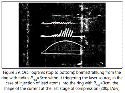
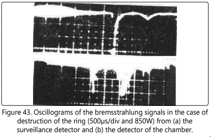
As noted above, by changing the operating mode of the source one can adjust the concentration of the atoms in the flux passing through the electron ring. The range of changes was defined by preset adjustment of the laser source. The laser radiation flux density on the target could be varied by changing the voltage on the capacitors of the discharge pump lamp and with the help of radiation attenuation filters. The entire range of working concentrations of atoms was almost overlapped. At a flux density of 2.5×10⁸W/cm2 (Na=5×1010cm-3) the ring totally or partially collapses (Figure 39). Figure 43a shows the oscillogram from the collector. It can be seen that the flux with a high concentration of atoms is injected into the ring, there appears a large bremsstrahlung signal, preceding the signal of ‘reverse’ injection). At lower densities of atoms the first signal is absent. The signal from the second detector operating in current mode is shown in the oscillogram of Figure 43b. The absence of the bremsstrahlung signal after the first pulse demonstrates the termination of ion accumulation in the ring. At 107W/cm2(Na=5×108cm-3) the bremsstrahlung from the ring with the detector sensitivity taken into account was not observed. Thus, it is possible to optimize the process of the ring loading with the ions when the laser source is properly adjusted. When the atoms are injected into the ring of a large radius (up to 35cm), which is then compressed, one can observe stable bremsstrahlung signals that existed until the destruction of the ring after compression. This experimentally recorded fact indicates the possible usage of the time of the loaded ring compression to increase the average charge of accumulated ions (Figure 38).
The experimental results show that the laser source of atoms is suitable for loading electron rings with ions in a collective accelerator.
The source operation showed the correctness of the design, the materials used as well as the high reliability. Control of the process of loading of the ring with the help of the laser source allows the accumulation of ions of different elements (up to uranium) to be optimized in the experiments.
Negative ions in the acceleration technology
Negative ions source
Various fields of science and technology urgently require the creation of intense negative ions source for use in high-energy accelerators in nuclear, atomic and applied research to study the fundamental processes of classical nuclear physics, as well as in programs on controlled thermonuclear fusion (CTF). The development of such sources has given an impetus to the design and construction of large tandem accelerator, which together with other facilities allow one to accelerate the heavy nuclei of some elements above the Coulomb barrier, thereby opening up new possibilities for the study of natural phenomena at the nuclear level.
In addition to this traditionally developed program, new applications of negative ion beams are currently experiencing rapid growth in chemical physics, geophysics, and surface physics. For example, the tandem-accelerator mass spectrometry is now being rapidly developed to study the precise isotopic composition of elements. Because of the relatively low energy of the electron affinity of atoms, the negative ions can easily donate electrons in collisions, thereby forming neutral beams. Accelerated negative ions are widely used to impregnate ions into semiconductor materials, in radiation damage, surface analysis based on Rutherford scattering, secondary ion mass spectrometry, X-ray fluorescence, depth profiling and many other areas.
Deeper understanding of the physical processes occurring with the direct participation of negative ions favored an increase in the amounts of information about their structure. This refers to the effects of radiation absorption in the stellar, including solar, atmosphere, to the electrical discharge and breakdown phenomena in electronegative gases, as well as to the processes in the Earth’s atmosphere. Operation of most sensitive detectors of halogen compounds, such as many types of pesticides investigated in connection with the problem of environmental protection relies on the formation of negative ions. Note that the use of negative ions requires the creation of a universal source, capable of producing beams of negative ions that contain the maximum number of elements of the periodic table. The review of the currently available sources shows that the efficiency and versatility of such sources depends to a large extent on the mechanisms of ion generation and the values of the electron affinity of these elements.
Laser plasma as a negative ions source
High efficiency of negative ions in different plasma and accelerator facilities has stimulated the development of intense sources. The currently available hydrogen ion currents are equal to 1 A in the pulse of the plasma sources. With increasing ion mass and decreasing energy of the electron affinity the intensity of negative ion beams decreases significantly. The obtained maximum intensities range from a few to hundreds of microamperes (Table 2.)
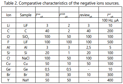
Table 2. presents comparative characteristics of the existing sources of negative ions of heavy elements with integral data output. Apart from the advantages of conventional sources, it is necessary to mention some drawbacks, namely:
1. Low emittance.
2. Use of secondary emission from the surface of a solid body; a number of serious shortcomings are usually noted.
3. Current density of negative ion emission is limited by the dielectric strength of the ‘plasma – extracting electrode’ gap and decreases with the size of the emission hole.
4. In the region of the emission hole it is necessary to provide the high gradient of the working material concentration for the efficient generation of negative ions and for reduction of their losses on the way to the emission hole.
5. Limitation of the beam intensity due to an increase in the permissible thermal loads on the anode in the emission hole.
6. Negative ion beam dispersion due to the action of the space charge.
7. Unavoidable presence of electronegative impurities in discharges.
When using a laser-plasma as a source of negative ions, these drawbacks are automatically removed or significantly restricted. When a laser-plasma spreads in a vacuum, there appear concentration gradients at the plasma boundary and the space charge of negative ions is compensated for up to large distances from the place of their formation, which contributes to simplification of their transportation to the destination point. Moreover, laser-plasma sources of negative ions have a number of practical advantages:
1. flexibility (the ability to obtain negative ions of any element of the periodic table);
2. sterility of selection of ions using a ‘dry’ vacuum (10-6 Torr);
3. wide variation in the location of the source with respect to external devices;
4. simple and compact design.
Optimization of the negative ion source operation requires information about the characteristics of ions, electrons and atoms, the concentration of particles and their local distribution in the region of generation, which is a very tedious task.
The validity of these estimates is confirmed by the existence of an optimum for formation of negative ions for 10.6µm radiation (2–5×10⁹W/cm2) and by the corresponding dynamics in q for 1.06µ. The integral emission characteristics of negative ions as a function of q are in the range from 10-3–10-4 for aluminum ions and 10-1 for carbon of the total yield of positively charged ions.
Conclusion
One of the most notable advantages of the ion source with laser-driven type is high charge state of the ions, which is achieved by the extra-ordinary high electric field gradient. The highest ionization state is measured in our experiments to be +28. One of the most important factors for the multi charged ion source as an injector towards the conventional accelerator is to have as high charge state as possible. By simply applying the metal target, the ionization state of all the ions might be united, being fully stripped, which should be confirmed in the future work. Such a high charge state is not easy to obtain in the existing ion source of the conventional accelerator. In general, laser-based multi charged ions can be an attractive option in near future to overcome limitations imposed on the charge to mass ratio in currently available ion source. This approach also shows the possibility of substituting the front end of the conventional accelerator system, which would greatly help for downsizing and lowering the cost of the accelerator systems [22-25]. The experiments with multi charged ions in JINR (Dubna) and CERN (Geneva) are in progress.
References

