Research Article
Innovative Slope Stability and Displacement Analyses
Department of Civil Engineering, National Cheng Kung University, Tainan City, Taiwan
*Corresponding author: Ching-Chuan Huang, Department of Civil Engineering, National Cheng Kung University, Address: No. 1, University Rd., Tainan City, Taiwan, Tel: 886-6-2757575 ext. 63160, Fax: 886-6-2383042, E-mail: samhcc@mail.ncku.edu.tw
Received: November 9, 2018 Accepted: December 21, 2018 Published: January 2, 2019
Citation: Huang CC. Innovative Slope Stability and Displacement Analyses. Madridge J Agric Environ Sci. 2019; 1(1): 7-13. doi: 10.18689/mjaes-1000102
Copyright: © 2019 The Author(s). This work is licensed under a Creative Commons Attribution 4.0 International License, which permits unrestricted use, distribution, and reproduction in any medium, provided the original work is properly cited.
Abstract
Conventional methods of slope stability provides a constant value of safety factor for the slope, providing no information of slope displacements and possible variations of safety margins along the potential failure surface. To overcome this drawback, an innovative approach is proposed here, which takes into account all limit equilibrium requirements originally adopted in the conventional slope stability analyses, with a displacement compatibility function and a hyperbolic shear stress-displacement soil model. The new method provides incremental slope displacements induced by internal or external stress (or safety status) variations. A case study on a well-monitored slope during a rainstorm showed that the measured slope displacement caused by an elevated groundwater table can be simulated using the proposed method along with hyperbolic soil parameters obtained in large-scale direct shear tests. The proposed method substantially strengthened the weakness associated with conventional slice methods, providing useful information of slope displacement induced by the elevated groundwater table.
Keywords: Slope failure; Slope displacement; Stability analysis; Disaster mitigation; Force equilibrium.
Introduction
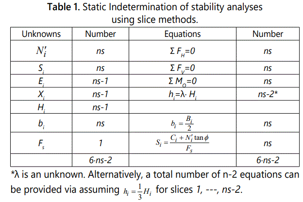
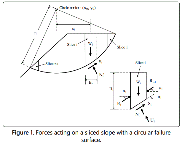
The slice method of slope stability was pioneered by Fellenius in 1920’s [1]. The original Fellenius’ method and the following updates constitute a major contribution to the practice and development of geotechnical engineering [2-6]. It is a well-known fact that the sliced potential failure mass is a statically indeterminate system [7,8]. Table 1 summarizes unknowns and equations for a potential failure surface with a total of ns slices. Figure 1 schematically shows the force acting on a potential failure mass with ns vertical slices, in which, >Wi, Ni and Si represent the self-weight, the normal force at the base, and the shear force at the base, of slice i, respectively. Fellenius [1] proposed a simplified scheme of slice method using a circular failure mechanism, as shown in figure 2. In this simplified scheme, only a part of criteria listed in table 1 was used, yet a static determinate system with a straightforward expression of safety factor (Fs) can be obtained as:


Where,
i: slice number (i=1, 2, …, ns)
Wi: self-weight of slice
αi: inclination angle of slice base i
c: cohsion intercept of soil
φ: internal friction angle of soil
ui: porewater pressure acting at slice base i
ℓi, Bi: the length of base and the width, respectively, for slice i.
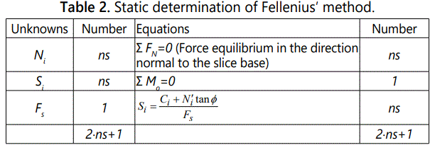
The static determinate conditions for the Fellenius′ slice method is summarized in table 2. Note that the force equilibrium in the direction normal to the slice base (Σ FN=0) does not take into account the influence of inter-slice forces. This method is based on an implicit assumption that the resultant inter-slice force acts parallel to the slice base, as pointed out by Whitman and Bailey [7].
Derivation of Displacement-Based Fellenius′ Method
In the following, local force-based safety factors (FSi) and a hyperbolic stress-displacement model will be incorporated in the Fellenius′ method. According to Σ FN=0, the effective normal force Ni′ can be expressed as:

According to Mohr-Coulombs′ failure criterion and the definition of local stress-based safety factor FSi:


where,
τfi , τi: ultimate shear strength, and shear stress, respectively, for slice i.
Sfi, Si : ultimate shear resistance and shear force, respectively, for slice i
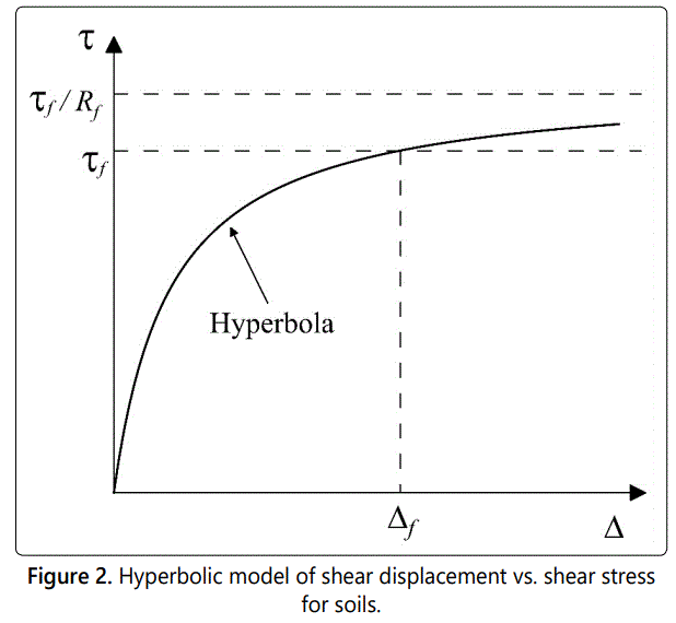
FSi: local force-based safety factor As shown in figure 2, where the shear stress (τi) vs. shear displacement (∆i) relationship is represented by a hyperbolic curve, expressed as [18]:


where,
kinitial: initial shear stiffness
K, n: material constants
Rf: failure ratio
σni′ : normal stress acting at the base of slice i
Pa: atmospheric pressure
Normalizing Eq. (8) using τfi:


Based on the definitions of local safety factors in Eqs. (5), Eq. (13) can be re-written as:

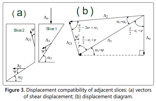
Introducing a displacement diagram [9] that satisfy displacement compatibility as schematically shown in figures 3a and 3b:

where,
ψ: agle of dilatancy
The displacement of slice i can be related to the vertical displacement at the top of slice No. 1 (Δo) using the following equation:

Equation (18) can be expressed as:

where,

Substitute Eq. (20) into Eq. (16),

Based on the principle of moment equilibrium at the center of circle, i.e.,ΣMoo=0:

Rewriting Eq. (22):

Substitute Eqs. (4) and (21) into Eq. (23), and re-arrange to solve for Δo:

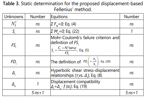
It can be seen that Eq. (24) is basically an inverted expression of Eq. (1), with additional displacement-related known parameters ‘a’,‘b’,‘ƒ(αi)’, and an unknown ‘Δo’. The static determinate condition for the extended Fellenius′ method discussed above is summarized in table 3. It can be confirmed that the extended method is also a static determinate system. It is noted that the unknown ‘Δo’ appears at both sides of the equation, indicating that an iterative procedure is required in calculating values of ‘Δo’. This situation is similar to that used in the calculatiion using the simplified Bishop′s method [2,19,20] which also required an iterative calculation for the safety factor of the slope. A convergence criterion of ε=1% is used here to detect the convergence of Δ0 :

Local Displacement-Based Safety Factors
The displacement at failure (Δf) can be obtained by using FSi=1.0 in Eq. (16):

Re-arrange the above equation to obtain Δf:

A displacement-based safety factor, FDi can be defined as:

Substituting Eqs. (19), (27) into Eq. (28):

Analytical Procedure in Computer Program
A computer program in Visual Basic 2010 (Microsoft, 2010) was coded based on the following algorithm:
1. Input analytical parameters, including slope profile, circular arc failure surface (rotation center, coordinates, and radius), and displacement-related parameters, K, n, and Rf.
2. Perform a conventional slope stability analysis using Eq. (1) to derive a constant value of Fs.
3. Calculate preliminary values of Ni′ using Eqs. (4), or calculate σ′ni using Eq. (12), by assuming FSi=Fs.
4. Calculate preliminary values of ‘a’, ‘b’, and f(αi) using Eqs. (14), (15) and (20), respectively.
5. Calculate preliminary value of ‘Δo’ using Eq. (24).
6. Calculate preliminary values of FSi (i=1,---, ns) using Eq. (21).
7. Calculate improved values of N′i and ‘a’ using Eqs. (4), and (14), respectively.
8. Calculate improved value of ‘Δo’ using Eq. (24).
9. Check the convergence of ‘Δo’ using Eq. (25). If not satisfied, repeated from step (6).
10. Calculate final values of FSi and FDi using Eqs. (21) and (28), respectively.
11. Calculate final values of ∆i using Eq. (19).
12. Calculate final values of internal stresses σ′ni and τi, using Eqs. (12) and (8), respectively.
Increments of Slope Displacement
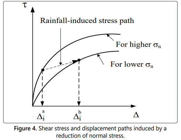
In calculating slope displacements induced by external and internal condition changes (e.g., loading, water table, and porewater pressure variations), two values of ∆i (or Δ0), namely, a slope displacement prior to the event (∆ai) and that after the event (∆bi) should be calculated, and the increment of displacement for slice i, occurs in that event is schematically shown in figure 4, and is defined as:

Case Study and Discussions
The studied slope locates in south-west foothill area of Taiwan. The slope is a part of highway No.18 which winds through a chronic landslide area. The landslide caused property losses and traffic problems in rainfall seasons, and therefore, was well monitored and studied [10]. Figure 5 shows the studied slope with points of inclinometer measurements and possible locations of slip surface [11]. The observed slip surface is simulated using seven segments of straight lines which are also shown in the figure. Underground water table observations were conducted in a borehole adjacent to the slope during the rain strom, and the recorded water table height is also shown in figure 5. The slope displacement during typhoon Herb in 1995 using the data of inclinometer measurements is 30 mm in the downward direction. Site exploration has shown that the slope mass consisted of colluviums, and the fragments of rock frequently showed high blow counts (N-value) of standard penetration tests. The N-value for the matrix material on-site was about 10. Probable values of φ in the range of 25°-30° are estimated for the focused slope. The cohesion intercept (c) for the slope mass has been back-calculated, and a probable range of c=30-40 kPa has been reported for the studied slope by ERRL [11]. Figure 6 shows the changes of conventional safety factors (Fs) for the studied slope due to the elevated groundwater table. For a range of internal friction angle (ϕ) ranging between 25° and 30°, and a range of cohesion intercept (c) ranging between 30 and 40 kPa, a reductions of Fs due to groundwater table rising for about 0.05-0.06 was obtained. Note that conventional slope stability analyses cannot provide information beyond this point and a reduction of Fs for 0.05-0.06 usually provides limited knowledge on the influence of groundwater table (or the effect of rainfall) to the performance of the slope. Figure 7 shows a typical example of shear stress-displacement relationships obtained in a large-scale direct shear test on a rooted undisturbed soil in south-west foothills of Taiwan [12]. The stress-displacement relationships are simulated using the hyperbolic model described previously. To account for the effect of confining stress on the shear strength increase of soils, the tensile forces of plant roots was treated as an increase of confining pressure, based on a verified theory of soil reinforcement [13]. Although a large-scale direct shear test was not performed for the studied slope, the well-simulated stress-displacement curves shown in figure 7 generally suggest the applicability of the hyperbolic shear stressdisplacement relationships to be used here. A more accurate analysis can be pursed in the future based on site-specific direct shear test results.
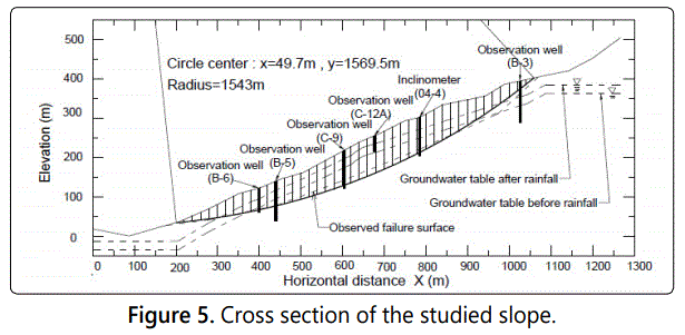
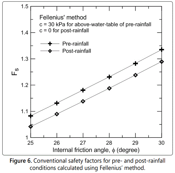
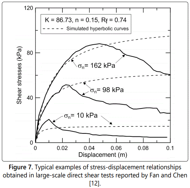
Figure 8a shows analytical values of horizontal displacements for at x=800 m where the inclinometer was installed. Three groups of curves are characterized by their Rf values, i.e., curves with higher Rf have larger curvatures. It is noted that the curve with Rf=0.9 is practically significant, in the sense that this measured displacement (δh=30 mm) can be simulated using specific values of ϕ between 25° and 30°. Also noted that these values of K, n, and Rf are similar to those shown in figure 7. The result of a special case of the nonlinear hyperbolic stress-displacement relationship, namely, a linearly elastic stress-displacement relationship (by using Rf=0 in Eq. 10), is shown in figure 8b. This plot shows that horizontal displacements calculated using the linearly elastic-plastic stress-displacement model with similar values of K, n, c, and ϕ are two to three orders different from those shown in figure 8a. This suggests that calculations of slope displacement using a simplified linearly elastic-plastic model is less realistic in this case, and should be used with caution. Figure 9a shows comparisons between local stress-and displacement-based safety factors (FSi and FDi) for the case of c=30 kPa, ϕ=25°, K=90, n=0.2, Rf=0.9. Based on the conventional constant-safety factor concept, values of Fs using Eq. (1) for the slope under pre- and post-rainfall conditions, are 1.04 and 1.08, respectively. Distributions of FSi and FDi for the pre-rainfall case reveal that a major portion of the potential failure surface are associated with FSi>1 (or FDi>1). Only small portions of potential sliding mass (close to the toe and the crest of potential failure mass) were associated with FSi<1.0 (or FDi<1.0) conditions. For the case of post-rainfall, the slope experienced substantial drops of FSi and FDi, along a major portion of the failure surface. It can be seen that a part of the slices experience FSi=1.0, indicating that ultimate failure conditions have reached at these locations. This observation is consistent with the observations that tension cracks developed around the crest of sliding mass [14], and is also consistent with the progressive failure mechanism proposed by Bjerrum [15], in the sense that a stress redistribution along the potential failure surface propagates from the slope toe due to overstressing at the slope toe. In the present study, it is shown that a critical condition occurs at slope toe because of a combined effect of high groundwater table and low overburden pressure. It is important to note that the use of displacement-based safety factors, FDi, is more advantageous than the use of stress-based FSi, in the sense that the difference of FDi between the pre-rainfall and postrainfall cases is larger than that for FSi. This allows a more detailed investigation of the safety status of the slope than that based on the distribution of FSi. Figure 9b shows the effect of ψ on the calculated values of FSi and FDi by using input conditions identical to those used in figure 9a, except that ψ=12.5° (=ϕ/2) is used for figure 9b. Differences between figures 9a and 9b can be hardly seen, indicating that input values of ψ have a negligible influence on the outcomes of FSi and FDi. Figure 10a shows calculated values of shear displacement (∆i) and horizontal displacement [= Δi ⋅ cos(αi - ψ)] along the slip surface for the same case shown in figure 10a. Shear displacements at close-to-crest locations are larger than those at close-to-toe. It can be seen that horizontal shear displacements along the entire slip surface are identical, reflecting the basic assumption of the proposed methodology, namely, a rigid body with no lateral compressive deformation of the slice. In the future, lateral compressions of slices can be incorporated in the proposed method to simulate the behavior of a laterally compressed sliding mass. Figure 10b shows an otherwise similar plot to figure 10a, except that ψ=12.5° is used in figure 10b. The influence of on the patterns of displacement along the failure surface is significant. By using a non-zero value of ψ=12.5°, the assumption of a rigid body becomes invalid, and the pattern of shear displacement mimics that of f(αi), as shown in figure 11. The non-rigid displacement behavior shown in figure 10b reveals another advantage of the proposed method, in the sense that various displacement patterns of the sliding mass can be simulated via the input value of ψ which dictates the shape of the displacement compatibility function f(αi)).
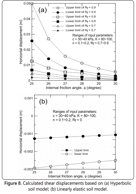
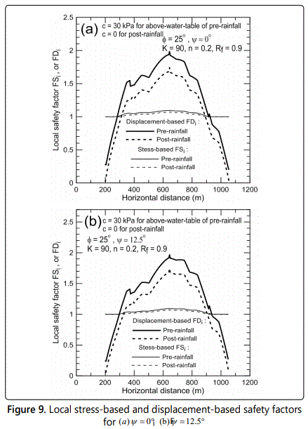
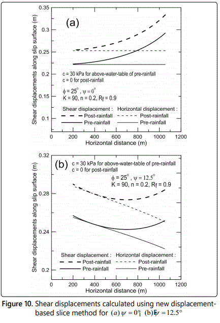
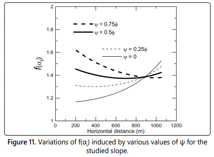
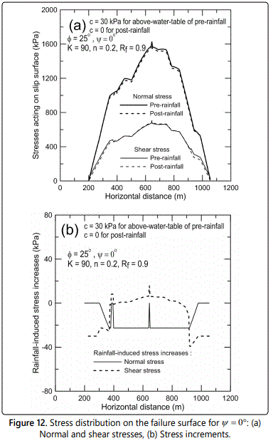
Figure 12a shows typical examples of mobilized shear and effective normal forces along the sliding surface based on identical soil parameters for figures 9a and 10a. Distributions of σ′ni and τi generally show good trend of internal stress distributions, in the sense that normal stresses along the failure surface increase with the increase of the depth of failure surface. This trend is consistent with previous studies on the internal stress along the failure surface [16,17]. Increases of σ′ni and τi induced by the rainfall (or the water table rise) are highlighted in figure 12b. Reductions in σ′i, associated with increases of τi along a major part of the sliding surface can be seen. In figure 12b, a normal stress reduction of 20 kPa prevails along the major portion of slip surface. Increases of shear stress are insignificant for a major portion of slip surface. At close-to-toe and close-to-crest locations where the values of FSi have reached the critical condition (=1.0), the slope experienced certain degrees of shear stress reductions, due to the stress re-distribution mechanism [18-20].
Conclusions
A novel improvement of a conventional slice method of slope stability is proposed here, providing significant information regarding the displacement of the slope subjected to internal and/or external environmental changes. The proposed method satisfies force and moment equilibrium criteria adopted in the original slice method, with additional displacement compatibility requirement and a hyperbolic shear stress-displacement soil model. A new static determinate system was attained by introducing displacement compatibility functions and a hyperbolic shear stress-displacement model for the Fellenius’ method. As a result, local displacement-based and stress-based safety factors along the potential failure surface are parts of the analytical solution. Based on the case study of a well-monitored slope during a rainstorm, the effect of groundwater table rise during the rainstorm, expressed as an incremental slope displacement, was computed using the proposed method. It was shown that the slope displacement measured during the focused rainstorm can be closely simulated using stress vs. displacement relationships obtained from a large-scale direct shear test, revealing the potential of the present method for further applications.
References