Research Article
Towards the Control of Inherent Vibration of Flexible Robotic Systems and Associated Dynamics: New Proposition and Model
1Division of Remote Handling and Robotics, Bhabha Atomic Research Centre, Department of Atomic Energy, Mumbai, India
2Homi Bhabha National Institute, Department of Atomic Energy, Mumbai, India
*Corresponding author: Debanik Roy, Division of Remote Handling and Robotics, Bhabha Atomic Research Centre and Homi Bhabha National Institute, Department of Atomic Energy, Mumbai, India, E-mail: deroy@barc.gov.in
Received: February 1, 2019 Accepted: April 17, 2019 Published: April 26, 2019
Citation: Roy D. Towards the Control of Inherent Vibration of Flexible Robotic Systems and Associated Dynamics: New Proposition and Model. Int J Robot Res Appl Autom. 2019; 1(1): 6-17. doi: 10.18689/ijra-1000103
Copyright: © 2019 The Author(s). This work is licensed under a Creative Commons Attribution 4.0 International License, which permits unrestricted use, distribution, and reproduction in any medium, provided the original work is properly cited.
Abstract
The domain of Flexible Robotic Systems (FRS) is one of the unique ensembles of robotics research that deals with various modes of vibrations, inherent in the system. The vibration, so referred, is completely built-in type and thus it is design invariant. By nature, the vibration in FRS is self-propagating and does not follow analytical modeling and rule-base in all applications. The asynchronous data fusion, emanating out of FRS is a challenging research paradigm till date, primarily due to the inherent characteristics in quantifying the output response of the system. Real-time assessment of vibration signature in FRS is a pre-requisite for establishing a reliable control system for any real-life application.
The paper focuses on new approach of modeling this inherent vibration of the flexible robotic system and brings out its effect on the associated dynamics of the FRS. Besides, the paper dwells on modeling & theoretical analysis for a novel rheological rule-base, centering on the zone-based relative dependency of the finite numbered sensor-units in combating the inherent vibration in the flexible robot. Besides, a new proposition is developed for assessing the decision threshold-band, signaling the activation of the FRS-gripper, using a stochastic model.
Keywords: Flexible Robot; Vibration; Rheology; Data Fusion; Sensor; Hypothesis; Algorithm.
Introduction
Characterization and dynamic analysis of Flexible Robotic Systems (FRS) is a challenging arena of todayʼs robotics research as the system is gaining foothold for a variety of applications in social & medical diagnosis. Although FRS is having an advantage of very low tare weight which is quite befitting for a large number of applications, yet the major bottleneck is its inherent vibration. This inherent vibration is totally built-in type, structure independent and gets manifested in two ways, namely: modal frequency & Eigen value. Several designs of FRS have been attempted by the researchers in past decade in order to alleviate this vibration but most of those trials have been unsuccessful. The problem gets even complicated when we attempt for multi-link design of the FRS, wherein various kinds of coupled effect & non-linearity crave in. It has been also observed that vibration in FRS is not time-dependent and the duration & periodicity of it canʼt be correlated with the task-space of the robotic system. Moreover, by nature, this vibration is self-propagating and it gets induced to the successive member of the FRS till the end-link as well as the end-effector/gripper. At times, vibration becomes self-generating and random too. Due to all these characteristics, it is very difficult to obtain a generic analytical model for the vibration in FRS. And, since modeling canʼt be attempted in a generic manner, usual rule-bases for adopting control algorithm for the end-applications are also unviable. The other issue, pertaining to analyzing this self-induced built-in vibration in FRS, is the modality of fusing the real-time data on vibration (amplitude & frequency). Since we need to evolve with a robust system for reducing this vibration & effect thereon, there is a need to design a system for asynchronous data fusion. Unlike the traditional approaches of sensory data fusion, FRS-based data fusion has another dimension for the analysis, viz. time-period, thereby signifying real-time operation of the FRS. In totality, this asynchronous data fusion ensemble has evolved as a challenging open research paradigm in recent past. Proper quantification of the output response, i.e. vibration signature is one of the challenges in executing the FRS. The problem gets even critical when we need to deal with multiple links of the FRS and/or limited number of elemental sensor-units, in contrast to traditional theories dealing with robust structural dynamics of Industrial Robotic Systems (IRS).
In all practical applications, the vibration signature in FRS gets assessed through multiple force sensors, spread over the links & joints of the FRS in real-time. The sensory data, so generated, is fed to a fusion model and the outcome becomes instrumental in establishing a reliable control system for the FRS. It is imperative that relatively better vibration signature can be obtained by agglomerating identical sensor units.
In this paper, we will focus on new approach of modeling this inherent vibration of the FRS and discuss its effect on the associated dynamics of the flexible robotic system. In fact, vibration models used hitherto in FRS have been found to be somewhat inappropriate for real-time monitoring & control of the payload, i.e. the object to be gripped at the end-of-arm tooling. Besides, the dynamics effect due to link-wise (zonal) distribution of the sensors in the FRS was largely unattended. In answering those lacunas, the present paper dwells on the modeling, algorithm and theoretical analysis of a novel rheological rule-base, centering on the zone-based relative dependency of the finite numbered sensor-units in combating the inherent vibration in the flexible robot. Besides, a new proposition is developed for assessing the decision threshold-band, signaling the activation of the FRS-gripper, using a stochastic model.
Control issues of FRS have gained research attention over the last few decades, which deal with novel techniques of control of system dynamics in real-time [1]. While perturbation method was tried for fine-tuning FRS-controller [2], direct real-time feedback from strain gauges was experimented too [3]. It is true that a robust dynamic model becomes very effective in understanding the behavior of FRS in real-time and the same becomes crucial for a multi-link FRS [4,5]. Feliu et al. attempted the control issue of a three degrees-of-freedom FRS using the methodology of inverse dynamics in contrast to strain gauge-based control [6,7]. The fuzzy learning-based approach for control of FRS was also reported by Moudgal et al. [8]. Specific metrics related to reduction of system vibration of a robotic gadget were attributed by Singer & Seering [9]. Various techniques for vibration attenuation & control in FRS have been reported hitherto, such as sliding mode theory [10], adaptive resonant control [11], online frequency & damping estimation [12] & integral resonant control [13]. Dynamic model & simulation of FRS based on spring and rigid bodies was established too [14]. However, modeling of the multi-link FRS using compliant sub-assemblies, such as spring-dashpot-damper, remains an open research domain till date.
It is to be noted that in experimental mode of modeling & control of in-situ vibration of FRS needs a strong encapsulation of data structure, data assimilation and finally, statistical analysis. Attainment of optimality in data fusion and decision fusion are two important facets in this context [15,16]. Likewise theories of Bayesian detection [17] and Adaptive decision [18] have been reported. Stochastic modeling & novel hypothesis testing-based decision theory have been delineated in a study by Roy D [19]. Various application-metrics of the developed hypothesis testing-based decision thresholding have been reported, viz. dissimilar sensor-cells in robotic gripper sensor [20], robotic slip sensory grid [21] and field robotic sensory system [22,23]. Based on the earlier attainments, we will propose here a new fusion rule-base for the real-time analysis of vibration data of FRS. Development of a test set-up & first version of the prototype serial-chain FRS (PAR) has also been utilized for the standardization of the design [24].
The paper has been organized in seven sections. An overview of the firmware of the multi-degrees of freedom FRS is presented in the next section. Details on the possible sources of vibration in the flexible robotic system and characteristics of such vibration have been discussed in the “sources of vibration in flexible robotic system and its characterization” section. Issues related to modeling on the real-time damping and dynamics are attributed in the “modeling of the damping & dynamics” section. Paradigms on data analysis with respect to dynamic control & stability of the FRS are discussed in the “dynamic control and stability of flexible robotic systems: data analysis” section. Simulation results for evaluating the vibration characteristics of the flexible robot, along with its hardware (prototype) are reported in the “simulation of flexible robotic systems: analysis of vibration & hardware set-up” section and the final section concludes the paper.
Firmware of Multiple Degrees-of-Freedom Flexible Robotic Systems
Although flexible robots have become favourable choice in several new applications because of slender design, light weight, small size-envelope & increased reachability in the workspace, yet the major bottleneck of the system lies with the effective control of inherent vibration. A widely-accepted engineering way of evaluating this vibration is to detect and measure the deflection of the FRS-member(s) in real-time. The formulation, modeling & instrumentation for such deflection measurement are pre-characterized and can be adopted with the help of miniature strain gauges and flexi-force sensors.
One important design aspect of small-sized FRS is to augment drive mechanisms at the base of the robot, in order to reduce the tare weight of the link sub-assemblies. Although it is possible to integrate miniature servomotor(s) at the respective joint-link interface of the FRS, our experience says that such FRS will prone to have unwarranted drooping from time to time during its actuation, which will degenerate in additional trembling of the FRS-ensemble. Hence, even though in-situ motor-driven (direct drive) FRS is compact in hardware, it is not the ideal design choice. In order to alleviate this problem, the optimal design approach is to use flexible shaft for the joint actuation. Flexible shafts transmit rotary motion over, under, and around ‘obstacles’. They have higher efficiencies and are more economical than gears, universal joints, belts and pulleys. By this modus operandi, all drive motors will be placed at the base of the FRS and respective joint will be actuated through flexible shaft, connected between the motor-output-shaft & the joint-shaft. Figure 1 schematically illustrates the layout of a serialchain two-link FRS, fitted with flexible shafts. The tapered cross-section of the links has been conceived to have less weight and better slenderness ratio. The FRS is having two links and two revolute type joints with no joint at the wrist. While the motor-tuple {M1 & M2} is located at the base of the FRS, the motor, M3 is responsible for the operation of the micro-gripper.
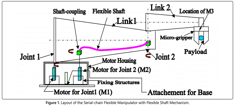
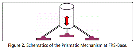
The drive for joint 1 is direct, i.e. coupled straight away with M1. The drive for joint 2 is through the flexible shaft. The driver end (left hand side) of the flexible shaft is the shaft of M2 and the transmission is carried over to the driven end of the shaft (right hand side) and thereafter to the joint. The system is to be mounted on a customized mechanism beneath the base, namely, the part, labeled as ‘attachment for base’ in figure 1. This is a sort of prismatic mechanism, positioned on a tripod, having linear movements along vertical Z-axis. Figure 2 illustrates a schematic view of the mechanism.
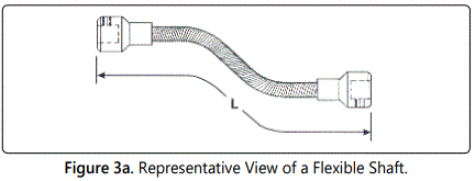
A standard flexible shaft, as available commercially, is shown in figure 3a. The major design estimation is its Length, i.e. ‘L’ as per the sketch. The overall length must be determined by closely approximating all bends and offsets. Also, the length of the flexible shaft should be measured along the centerline of the shaft. In other words, in case of flexible robot, ‘L’ should be selected considering enough clearance apart from the normal distance of separation between Joint 1 & Joint 2.
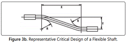
The bend radius (R) is an important dimension of a flexible shaft mechanism, besides other two dimensions; namely, ‘X’ & ‘Y’ (refer figure 3b for details). While ‘X’ is to be selected based on the total span of transfer of drive from joint to link of the FRS; ‘Y’ will be instrumental in combating torsion of the flexible shaft & link thereof.
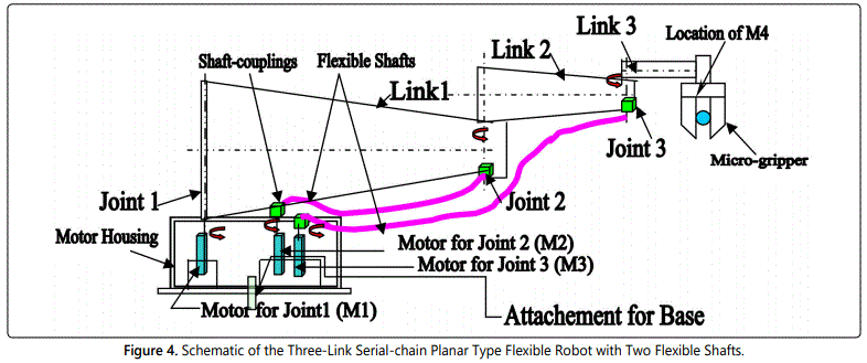
The firmware of serial-chain FRS with three links & two flexible shafts is very crucial from the angle of system dynamics & control of vibration. Figure 4 presents the overall schematic of the design, wherein motor for the third joint (M3) will also be at the base, along with M1 & M2. The motor, responsible for the actuation of the gripper is indexed as M4 here. The final prototype is to be made in modular fashion ideally, so that links can be detached easily as and when required in order to smoothen the dynamics in real-time.
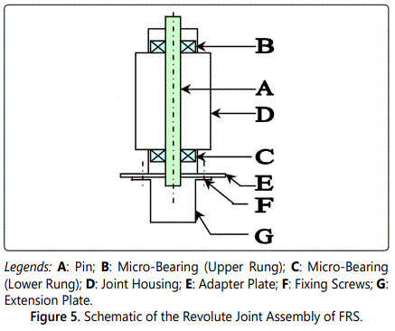
With reference to figures 1 & 4, it is to be noted that actual dimensions of the tapered links are in mm. range and much smaller than the visual impressions of the sizes. The revolute joints need to be constructed as simple bearing-supported pin joints, with an extended flange at the bottom. Figure 5 presents the detailed schematic of the revolute joint to be fabricated.
Sources of Vibration in Flexible Robotic System and its Characterization
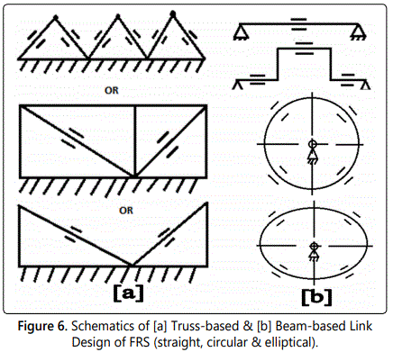
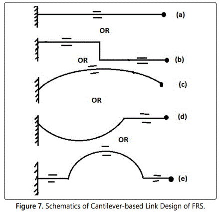
It is to be noted that inherent vibration of the flexible robot is directly proportional to the number of degrees-of-freedom of the FRS. Accordingly, combating such vibration, in coupled form in most of the time, becomes tricky and becomes model-dependent with input from multi-sensory data fusion metrics. The sources of this built-in vibration in FRS can be categorized in two groups, viz. a) vibration: based on location of the members & b) vibration: based on type of members. Now, location-wise, sources of vibration in FRS are the following: a) at the end-effector; b) at the distal link; c) at the rotary-type joints and d) at the flexible shafts. The sources of vibration as per the type of FRS-members are: a) truss-based; b) beam-based; c) cantilever-based & d) flexure-based. Vibration signature from the respective FRS-member, in general, will be ascertained through an ensemble of base-matrix (for housing sensing elements) and the frame of the member. For example, for truss-type members, it is the composite deflection that matters and the vibration needs to be evaluated from the interlinked structure of the particular member, as and when those are strained within elastic limit. In case of beam-based FRS-member, the FRS-member will have microbeam and the force sensing mechanism will be based on beam deflection principle. Now a particular FRS-member may have multiple beams embedded in it, each having its own characterization. The placement of those beams inside the FRS-member is also another technological challenge. Besides, layout of those ‘beams’ should also be prefixed. A standard way of placement of beam-members in FRS is matrix layout; either rectangular or circular. Nonetheless shapes other than these two can also be thought of for layout design, e.g. elliptical or triangular. In case of cantilever-based FRS-member, FRS will have one or more cantilever member, having relatively larger deflection potential at the ‘free’ end. Cantilever-type FRS-members do possess easy potential for affixing sensing element(s) as well as better relief at the nonfixed end. So far as flexure-based design of FRS-member is concerned, the member will have multiple flexible thin sub-members, which can be parked over the same supporting frame. Flexure-members will have base sensing member in an integrated fashion. Flexure-members must necessarily be designed as well as fabricated as thin & light-weight as possible. Thus selection of material and manufacturing method are very important for flexure-based design of FRS-members. The customized design of flexure-based members should have thin section, as best as possible.
Let us take a close look at the schematics of the vibration classification in FRS, based on the member-types. Figures 6a and 6b present the possible variations of truss-based and beam-based link design. Locations of the strain gauges are depicted as ‘=’ legend in figure 6 & afterwards. Likewise, five possible variants of the cantilever-based link design are illustrated schematically in figure 7, comprising of straight, step-straight, curvilinear, curve-straight & arch type. By virtue of the cantilever effect, strain gauges at the respective pick-up locations are more sensitive & thus effective for the FRS.
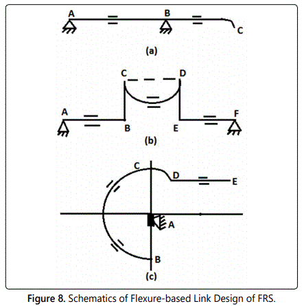
In flexure-based link design, we have the combination of beam bending as well as effect of cantilever together. Figure 8 schematically shows three feasible variations of this design.
With reference to figure 8, while scheme (a) is just an extension of the normal beam-based design, wherein the extended portion (BC) is responsible for creating the flexure Likewise, for scheme (b), we have blind - type flexure member (CD), bounded by horizontal as well as vertical beam/column members, like AB, BC, DE, & EF. Of course, it is to be noted that there will be characteristic differences between ‘open ended’ flexure member (like BC of scheme-a) and ‘blind-type’ flexure member (like CD of scheme-b). Deflection of strain gauges for flexure member is interesting to be noted too. The design scheme (c) is a combination of circular beam member (BCD), open-ended flexure member (DE) & a vertical column member (AB).
Strain gauges and flexi-force sensors, mounted on each link of the flexible manipulator (as per design: 5 strain gauges and 2 flexi-force sensors per link) will act as prime source of detection of the vibration in real-time, backed up by indigenous electronic circuitry hardware, as depicted in figure 9.

Modeling of the Damping & Dynamics
The multi-dimensionality of the in-situ vibration of the FRS, as detailed out in the last section, needs subtle mathematical modeling. The spring-damper-dashpot design scheme is the most optimal tool for the vibration analysis of FRS as it has inherent uncertainties and real time vibration control issues. As a matter of fact, this in-situ vibration-based method has become prudent in design synthesis for FRS due to its in-built nature of the range of dimension of the parameters. Before detailing out the modeling scheme, we need to take a closer look at the characteristics of a FRSmember when subjected to in-situ vibration (both inherent as well as external). This phenomenon has been simulated through the actuation of various spring-elements in unison, which are attached to the FRS-member.
The FRS-body will have member(s) mounted on mechanical springs, in order to realize spring-dashpot-based modeling of the FRS-member. Thus, those as-modeled spring-mounted members will act as in-situ vibration source, which will be helpful in assessing the overall deflection of the system.
The overall FRS architecture will have decent deflection scheme: the first is the inherent deflection/vibration of the mounting spring and the second one is the deflection of the links & joints. This conjugate deflection paradigm is the crux of the controller design of the FRS.
It is to be noted that design of the spring elements is a vital aspect of the design ensemble. There can be various design-models of the spring elements/members, which will be mounted/fixed directly over the link of the FRS in the model. Another interesting feature of this spring mounted modeling structure is to have couple of ‘branches’ (just like ‘tree branches’) of the different spring elements and/or spring-dashpot system. The later design-model, viz. spring vibration damper (dashpot) system will be self-compensated and the resultant vibration, generated thereof, will be the optimal amount required for stimulating the FRS-ensemble.
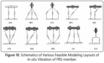
The disposition of a specific FRS-member under in-situ vibration can have several incarnations so far as damping model is concerned. Some of the feasible design ideations of this damping model are illustrated in figure 10. As can be observed from figure 10, two types are emerging, viz. a) Type-I: horizontal member: spring-mounted (Design Schemes: ’A’, ‘D’, ‘E’, ‘F’, ’G’, ‘H’, ‘I’) & b) Type-II: vertical member: spring-mounted (Design schemes: ‘B’, ‘C’, ‘J’).
It is to be noted here that design option for vertical/column members are limited, as the layout of the springs will not undergo major variations. On the other hand, horizontal members will have number of variations possible, owing to the layout of the spring member(s). It may also be observed that the fundamental aspect of the disposition of the spring metric (for horizontal members) is essentially multi-spring type, which is the crux of the spanning layouts. Multiple springs do give rise to options for enhanced compliance and with various permutations of spring-layout, modeling of the flexibility of the overall FRS-structure gets boosted up. Thus, both Type-I & Type-II model variants of vibration design play a big role will in characterizing the overall design ensemble of the FRS. One interesting feature of the spring-layouts shown in figure 10 is the individuality of the spring-elements, irrespective of the members (horizontal or vertical) thereof.
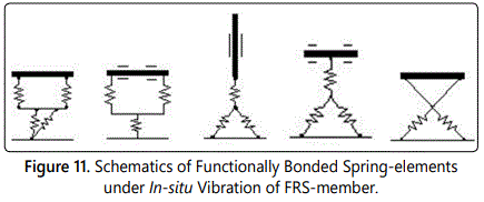
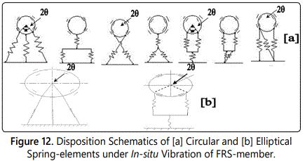
We will now deal with another layout, wherein disposition of the spring-elements can be functionally bonded and/or crisscrossed with fellow spring-element(s). Crisscrossing layout is a unique call of design, wherein two spring-members are ‘crossing’ each other to form an ensemble. In other design-layouts (refer figure 10) we have incorporated spring-members only in one direction, i.e. the spring rheology (tension and/or compression) was based on uni-directional arrangement. In fact, this sort of layout is entrusted to provide more subtle input to characterization of real-time damping. Figure 11 illustrates the schematic of the spring-layouts, using horizontal as well as vertical member. Let us now investigate other two types of design layouts under in-situ vibration-based layout, viz. ‘circular member: spring-mounted’ & ‘elliptical member: spring mounted’. Elliptical members will have similar design layouts as of circular type. Possible design variants with circular & elliptical members are schematically shown in figures 12a & 12b. Most of the features of circular-member & spring-element types (i.e. angle 2θ) remain same for elliptical members too.
The spring-damper-dashpot design theme is the most crucial aspect of flexible robotic systems due to its inherent uncertainty and real-time vibration control issues. The design model of this in-situ vibration system in FRS has been schematically shown in figure 13.
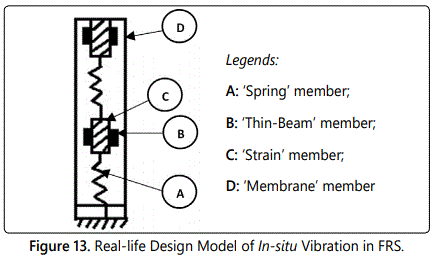
As evident from figure 13, ‘A’ & ‘D’ have mutual sharing of kinetics, while the effect of that will be arrested by ‘B’ & ‘C’. Since this design is related to forcing function of spring system or spring-mass-damper system, we have enough room to imbibe the concept of interval mathematics to solve the force displacement tuple. It is true that the principles of interval mathematics can be adapted to other categories of designs as well, but we will explore the postulation with in-situ vibration-based method of design first. In this context, we have for each design variable, ‘X’ in ‘ℜ’ (‘ℜ’: 3D space in real-time), a close association of parametric range (end-values) such that {X}:→ [X̲ , X̄] or → [Xmin, Xmax] in ‘ℜ’. These two range-values of ‘X’ will be experimentally determined and/or simulated a-priori. Hence, as explained in figure 13, we will have a combination of four design variables, pertaining to ‘A’, ‘B’, ‘C’, & ‘D’, which will have following paradigms:
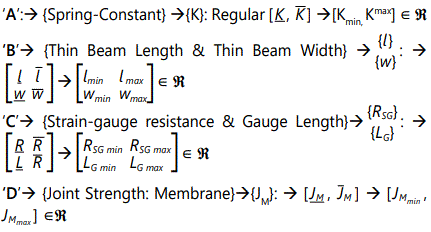

The formulation & computation of these interval matrices are crucial for the calibration of the sensing elements of the FRS.
Now, while dealing with a group of design variables like in this case of FRS‘, A’, ‘B’, ‘C’ & ‘D’ (i.e. four variables) or in expanded fashion 6 variables, we can define ‘Constraint Satisfaction Problem’ (CSP). By definition, CSP is formulated by a set of variables, {V}={x1 x2 ... .... xn} along with a set of ‘Constraints’ or equations {E}={c1 c2 ... ... ... cn} over interval domains: {[x1] [x2] ... ... .[xn]} . The formulation of CSP is essentially design-specific, i.e. for a particular design of the force sensor we will have one CSP formulated. Hence, each CSP can tackle a group of new variables, pertaining to the tuple of {V} & {E}. Damping model can be established mathematically using this lemma.
Dynamic Control and Stability of Flexible Robotic Systems: Data Analysis
The dynamic control of FRS is essentially data-driven and postulation-based, as generated from the damping model. Figure 14a schematically shows the sensory data space (‘F’) of the FRS, distributed into 3 zones viz. Ω1, Ω2 & Ω3, totaling ‘N’ sensor-units. As explained earlier, these ‘N’ sensors are laid over the links & joints of the FRS to capture vibration signature. We define a pair of logistic parameters {ui} & {uj}∈ ℜ that signifies inter-zonal influence pattern of the sensors. For example, ‘u1 ’ & ‘u2 ’ are interacting in Ω1, corresponding to two sensor-cells in zone-1 of the FRS. The territory of ‘influence’, between two sensors, is limited by the physical location of the FRS-links/joints. This conceptual facet is indexed as an imaginary segmented partition-line, viz. ‘Lij’ as shown in figure 14b.
As an extension of figure 14a, we have designed multi-sensory data space for the FRS, as shown in figure 14c. With the identification of generalized sensory zone (Ωp), individual sensor-elements have been indexed, e.g. ‘i’ & ‘j’, inside each zone. The cumulative effect of the inherent vibration of the FRS will be assessed through ‘Central Field Locator’ (CFL) numerically. The global value of CFL, i.e. CFLG will be computed in two ways. The first technique is a direct method using geometry, wherein geometric paradigms of computing CFLG is obtained using the properties of ‘Relative Dependency Triangle’ (RDT), as shown in figure 14d. On the other hand, the second approach is to have a weighted mean of all local CFLs, i.e. CFLL in the data space. We also observe that larger the area of RDT better is the sensory layout inside the field ‘F’ and ease for computing CFLG.
We have proposed stochastic model-based analysis of real-time vibration data of the FRS. The tool for doing such analysis is based on testing of statistical hypotheses. We define the hypotheses as System Dampening Done [SAD] vs. System Dampening Failed [SAF] respectively for Alternative Hypothesis (H1) and Null Hypothesis (H0). We define “System Dampening” as that very activity wherein the controller of FRS starts actuation and thereby initiates the full robotic cycle by manoewvring its joints. We prefer to adhere to the bi-modal hypothesis paradigm and represent the inherent fuzziness in decision-making process with ‘white noise’, having a relatively higher value of Signal-to-Noise Ratio (SNR).
Nonetheless, these two hypotheses have been re-modeled from real-life perspective as shown below, in-line with earlier work [19,20,22]:

where, Xi: Observation vector of the ith sensor-unit; Φi: Noise vector at the ith sensor-unit; Yi: Actual detectable signal vector and N: Total number of sensor-units in the FRS.
The a-priori probabilities of ‘H0’ and ‘H1’ are: P (H0) = P0 and P (H1)=P1. We assume all of these ‘i’ sensors (∀ i=1,2......N) have observations at the individual detector level, denoted by, Xi ∀ i=1,2......N., namely at links, gripper & joints. Now, each detector employs a “Decision Rule”, in order to make a decision-vector ‘ui’, which is the localized logistic metric. Let, logistic parameter, {ui}, ∀ i=1,2......N be defined against individual sensor-cells, such that, ui=0, if H0 is true and =+1, if H1 is true. We also consider the activation syntax of the data fusion to follow serial path. Nonetheless, the set {ui=+1} is to be arrived at by considering a cut-off value, ζ, in the following manner,

where uS+ is mapped with actual measured data vector as,

We further assume that the observations at the individual sensors of the FRS are statistically independent and the conditional probability density function is described by, P(Yi/Hk), ∀i=1, 2, N &∀k= 0, 1. The Global ‘U’, viz. ‘UG’ will be an extrinsic function of all the elemental fused data, ‘ui’, i.e. {UG}=f(u1, u2,.........,uN). The proposed method of inference relies on a ‘variable limit’ or dynamic threshold, which is estimated through a mathematical model. The location of the dynamic threshold limit is dependent on the confidence level for rejecting ‘H1’, chosen a-priori, i.e. Type I error numerically.
After processing sensor-wise outcome, we will have a logical unified output from FRS-system controller considering the set of ‘ui’ as {ui}=[0, 1]. The model culminates in a non-zero value of UG with an unbiased evaluation, so far as the actuation of the sensors is related. We define this sensory model for UG as,

where, {ui}: localized decision for the ith unit-sensor, ∀i=1,2,....,N; ‘N’: total number of unit-sensors activated in the FRS; x*,y*: refined coefficients, respectively for the ith1 & jth unit-sensors, computed as the product of ‘ζS’ (effect due to successiveness) and ‘ζL’ (effect due to geometric location); p: relative weightage of the ith unit-sensor and q: relative weightage of the succeeding sensor, i.e. (i+1)th. unit-sensor, where 0 ≤ p,q ≤ 2. We may note that this model is specific to sensor location (i.e. zone of the FRS), wherein relative dependency of one unit-sensor over the preceding ones is getting priority. The new model, proposed in eqn 4, relies on the neighbourhood effect of the FRS-sensors in a numerically compact manner, as the product of the two factors on the right-hand-side of eqn. 4 will always be less than or equal to 1.0.
The model does not consider backtracking of unit-sensors, i.e. it only considers sensors that are ahead of the specific unit-sensor, based on the physical disposition of the zones inside FRS. We also assume that in eqn. 4, {ui+1}|i=N=0. The conjugate parameter (x*,y*) has been augmented based on the logic that the fused data (UG), computed for a specific (i-j) segment of the sensory grid, is over and above what has occurred already in all preceding (i-j) segments. Finally, we model {x*, y*} as,

where, ‘dΩi’, ‘dΩj’ & ‘dij’ are respective linear inter-nodal distances of the RDT, as per the geometry of figure 14d. Thus, we have, ζL=1+dr,R (respectively for ith & jth unit-sensors), where dr=dΩi/dij and dR=dΩj/dij. It may be noted that the minimum value of ‘dr,R’ will be 1.0. In fact, if we adopt ζL=1-dr,R metric, then numerical complexities/fuzziness will appear in the fusion model. Although dij≠0, dΩi & dΩj can be zero, i.e. when both the unit-sensors i,j are located at the field-centre (CFLG); but that type of situation is highly unlikely. Obviously, in such a case, we will also have dr,R=0, followed by x*=y*=0. We can deduce a relationship between dr & dR using the geometry of RDT as,

Now, the fused decision regarding the selection of test hypothesis will be ruled by the evaluation paradigm, decided a-priori. In our model, we use ‘dynamic threshold band’ and the numerical value of the mean threshold (λThreshold-mean) as the evaluation metric. We define the evaluation metric as: if UG ≥ λTh-mean, then accept H1, otherwise reject H1. But, along with discrete acceptance or rejection, we will also encounter one fuzzy-zone, signifying in-decision regarding the acceptance or rejection of H1. Numerically, this in-decision zone will be directly proportional to the width of the threshold-band.
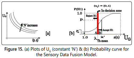
Using an exponential fit for the probability distribution of figure 15a, the probability of alternative hypothesis becomes,

In eqn. 7, ξ symbolizes minimal sensory activity inside the zones, while s(n) signifies the gamut of the maximum possible values of UG for various numerical combinations of (p,q). However, the boundary values for UG (∀ui=+1) will be guided by nine distinct values, for various permutative combinations of (p, q), where {p, q}⊂[0,2], all functions of ‘N’. Although there can be innumerable numerical combinations of (p,q) in-between these limiting nine cases, the boundary value of UG will always be guided through these nine gamut. We observe from the plots in figure 15b that for constant ‘p’, UG decreases as ‘q’ increases; the highest value of U;G being for (p=0,q=0) tuple, while the lowest is for (p=2,q=2). The mathematical way of re-representing UG as function of ‘N’, corresponding to different attributes of (p,q) tuple is detailed in a study by Roy D [22]. A comparatively larger value of UG will have more bandwidth to accommodate λTh, i.e. decision-making will be easier in such cases. Graphically too, it will enhance the ideation of rejection/acceptance of H1.
The dynamic threshold band is to be selected optimally using “Hypothesis Error Based Threshold Evaluation Method” (HEBTEM) [19], wherein user-specified value of probability of Type I error is fed as input. For example, estimation using “98% confidence level” (i.e. probability of Type I error as 0.02) essentially declares the situation of ‘SAD’ with 98% certainty. We shall now investigate the situation in order to select the dynamic threshold using HEBTEM. A graphical representation of the probability curve for ‘H1’ is plotted in figure 15a using {ui}=[0,1], characterizing the threshold-band with three parameters, viz. ‘A’: λTh-initial; ‘B’: λTh-final and the mid-point of the band as: λTh-mean.
The mean-value of the dynamic threshold (viz. λTh-mean in figure 15a) can be estimated using the statistical confidence level (α), i.e. probability of Type I error, as stated below. Here ‘x’ & ‘f(x)’ represent individual decision-vector of the unit-sensors and the exponential curve for P(H1) respectively, vide eqn. 7 while [s(n)]max signifies the maximum value of UG. The model can be mathematically expressed as:

However, choice of ‘α’ will largely depend upon the value of ‘s(n)’, i.e. how intense is the effect of relative dependency in the zonal sensor-grid or to that extent, how large is (p,q) tuple. Nevertheless, a stricter level (i.e. lower value of α) will lead to a tougher strategy for accepting SAD, i.e. H1. The planar area of the threshold-band, i.e the fuzzy-area of in-decision can be computed as:

HEBTEM-based data analysis for ‘H1’ & ‘H0’ has been invoked in understanding the attainment of stability of the FRS in real-time. Vibration signature of FRS members does affect a lot in determining the stability as very minute variation therein (in the order of one-thousandth) can be instrumental for dampening the FRS. The development of HEBTEM does provide a unique platform to test various fusion models (such as model shown in eqn. 4) as per the application scenarios. Thus, in this case of FRS, we have used the paradigms of HEBTEM with a changeover of the fusion model. The sole goal of this treatment is effective usage of the developed rule-base for a new domain of robotics research, namely, flexible robotic systems.
Simulation of Flexible Robotic Systems: Analysis of Vibration & Hardware Set-Up
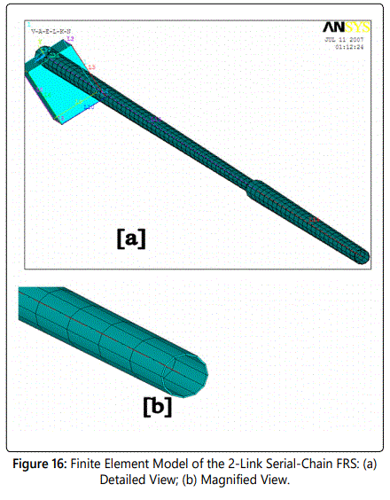
The serial-chain flexible robotic systems, as shown in figures 1 and 4, were modeled in 3D and finite element analysis (FEA) was performed in order to obtain the natural frequencies of vibration of the gripper under different modes. Due to the slenderness of the FRS designed, meshing for the FEA gets critical. Modal analysis of the FRS was carried out with the meshed layouts in order to obtain natural frequencies of vibration. The other important aspect that gets revealed is related to the characteristics of vibration for a ‘closed-chain’ structure of the FRS. We will examine the differences in FEA-model as well as vibration signature for both serial-chain & closed-chain FRS. We will also highlight the effect of this inherent vibration on the gripper-end. For the FEA, we have selected two materials, viz. Kevlar & Carbon Fibre Reinforced Plastic (CFRP). FEA has been made and simulated thereof for both these materials in order to obtain the relative advantage of those in real-life firmware of the FRS. Although closed-chain FRS is a bit advantageous for the control of inherent vibration due to its structural robustness, serial-chain FRS is also competitive. The piece-wise approximation of the physical domain of the FRS provides good precision even with simple approximating functions in the FEA that was invoked. Figure 16 illustrates the FE-model of the two-link serial-chain FRS.
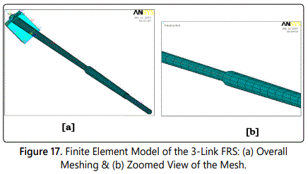
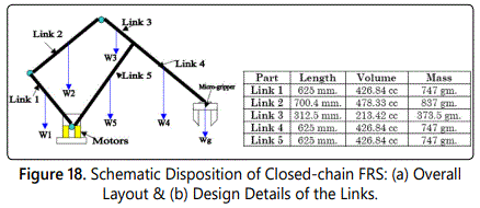
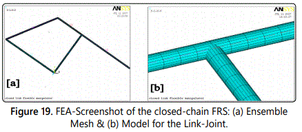
Figure 17 illustrates the FEA model of the three-link FRS. The finite-element analysis was carried out using the following data, viz. a) modulus of elasticity (for CFRP: 77,000,000 Psi or 531 kN/mm2 or 531 GPa & for Kevlar: 18,000,000 Psi or 125kN/mm2 or 125 GPa); b) Shear modulus (for CFRP: 750 N/mm2 & for Kevlar: 1540 N/mm2); c) Density (for CFRP: 1.75 gm/cc & for Kevlar: 1.44 gm/cc) and d) Tensile strength (for CFRP: 820,000 Psi or 5,656 N/mm2 & for Kevlar: 525,000 psi or 3621 MPa or 3621 N/mm2). Linear 2-node ‘BEAM 188’ (3D linear finite strain beam) element was used for the modeling of the links of the FRS which has got six degrees-of-freedom at each node. On the other hand, ‘COMBIN7’ (3D pin or revolute joint) element was used to connect the links through revolute joints in the finite element model. Capabilities of ‘COMBIN7’ include optimal modeling for joint flexibility (or stiffness), friction, damping & certain control features. Besides, this element possesses large deflection capability, by which a fixed local coordinate system can move with the joint. In order to benchmark the vibration signature of multi-link FRS, FEA was carried out for closed-chain design of FRS too. The schematic disposition of a typical closed-chain FRS, geometric design details of its links and its ensemble mesh are presented in figures 18a, 18b and 19a respectively. It is to be noted that mesh-model for the joint in closed-chain FRS is crucial, unlike the case of serial-chain FRS, which is similar to a ‘T-joint’ (refer figure 19b).
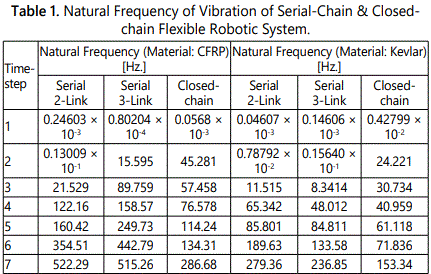
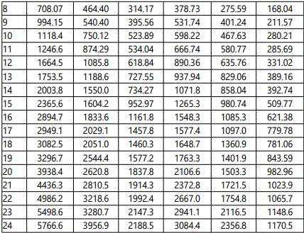
Both serial-chain & closed-chain configuration of FRS have been simulated for FEA under vibration mode in order to evaluate the natural frequencies of vibration under different modes. Primary vibrational analysis has been made in modal solution module, so as to identify the natural frequencies and the response behaviour of the FRS-structure to it. Modal analysis does not take any load data into account; it only requires a constrained body having mass defined. The study has been categorized for both CFRP & Kevlar, which educates us about the relative preference for the selection of the material for manufacturing. Natural frequencies of vibration have been evaluated through FEA for both 2-link and 3-link structure of the serial-chain FRS as well as for the closed-chain FRS. Table 1 presents some representative values of the natural frequency of vibration for these three layouts of the FRS. The ensemble contains 25 data-set from the initiation of the simulation and 15 data-sets from the trailing side. This has been made judiciously so as to bring out the relative alteration in the numerical values of the natural frequencies of vibration. The data-set revels that although serial 3-link FRS has got higher natural frequencies of vibration till sixth time-step over its 2-link counterpart, it gets dampened over the higher time-steps. Closed-chain configuration of FRS shows even better result with reduced values of the natural frequencies of vibration, barring few initial time-steps. Likewise, Kevlar shows slightly better results over CFRP for all models of FRS so far as the inherent vibration of the system is concerned.
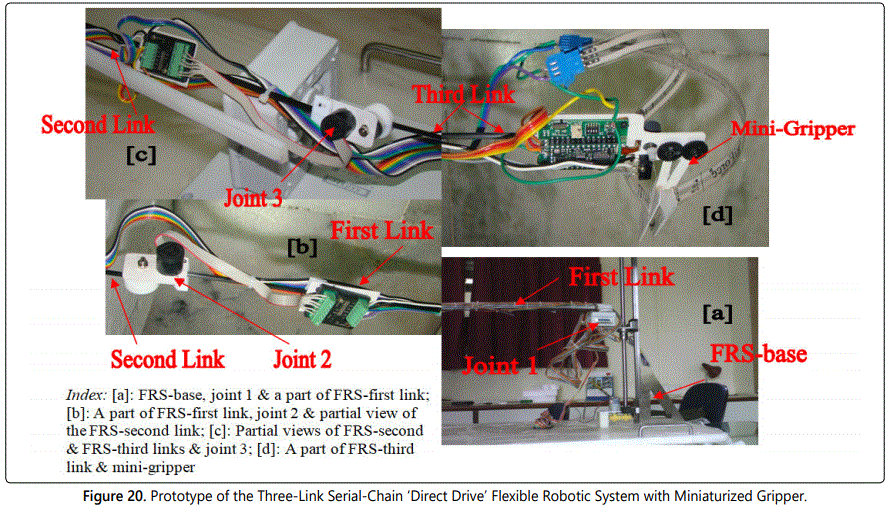
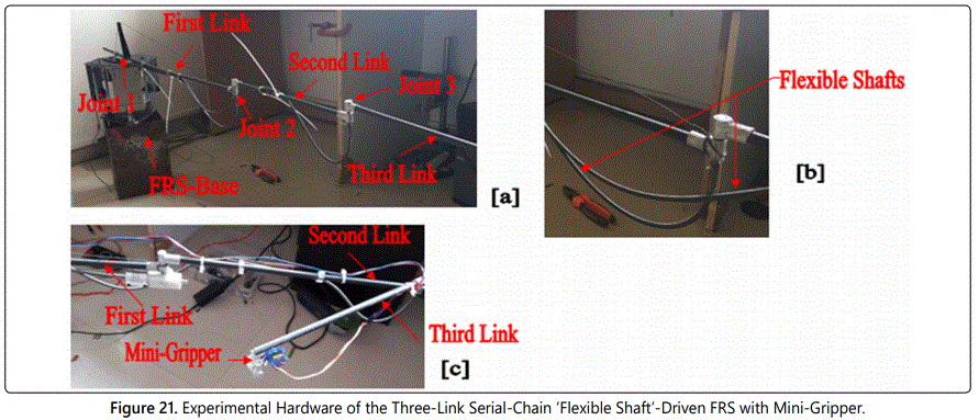
The FEA-based simulation of various varieties of FRS has made a strong foundation for the hardware manifestation of the systems. So far as application of the FRS is concerned, the ‘end-effector’ of the gripper plays a salient role. We have successfully developed two variants of serial-chain FRS having revolute joint-actuated three non-identical links & one miniaturized gripper at the end of the distal link. Figures 20 and 21 illustrate the developed hardware for the FRS-variants. The FRS, shown in figure 20 is actuated by servomotors placed at the joints unlike the other hardware shown in figure 21 wherein the actuation has been achieved via flexible shafts. The designs of the grippers are also novel and quite diverse from one another. Since the prototype FRS of figure 20 is of a large horizontal span of 1.5 meter, the photographic view is shown in four sub-assemblies, i.e. figures 20a to 20d. Overall disposition of the experimental hardware of the flexible shaft-actuated FRS is shown in figure 21a. Flexible shafts, responsible for actuating joints 2 & 3 are zoomed in figure 21b and interfacing of the mini-gripper with the FRS is snapped in figure 21c.

It is important to note that although simulation results for closed-chain FRS are impressive from vibration point of view, the configuration puts hindrance for many practical applications due to its involved layout. In contrast, serial-chain FRS can be fabricated in a compact fashion and the overall slenderness of the system becomes highly advantageous for application fields. As we have shown that the in-situ vibration of FRS is a multi-dimensional ensemble, we won’t achieve much significant result just by changeover of the design layout. With all these practicalities in mind, we went forward with the fabrication of the two versions of the serial-chain FRS as the design prototypes.
Conclusions
We propose new models for in-situ vibration signature of a multi-link flexible robotic system using spring-dashpotdamper and strain gauges. The vibration characteristic of multi-link FRS is quite different from that of single link flexible robots due to the coupling effects of joints & flexible shafts. Although the natural frequencies of vibration of FRS are dependent on the layout of the FRS (serial-chain vs. closed-chain) and its material of construction, the significant contribution does emanate from the drive system of the FRS-joints and run-time program. Scientifically ascertained locations of augmentation of strain gauges on the FRS-links play a crucial role too in the overall target of achieving smoother control of the system dynamics. The present research builds up an optimal foundation for analyzing inherent vibration of flexible robots using strain gauge-based measurement as well as stochastic model-based fusion of sensory data. At present, detailed simulation on the strain gauge layout-based vibration model is underway. Besides, piecemeal experiments are also progressing to study the effect of sensory placement paradigm. The results of these exercises will be reported in due course.
Acknowledgement
Author acknowledges the help rendered by Shri Stianshu Das, B.Tech student of Indian Institute of Technology, Kharagpur in performing Finite Element Analysis of the FRS structures as part of his internship project. The technical assistance provided by the engineers of M/s Devendra Fabricators, Nashik, Maharashtra and M/s SVR Infotech, Pune, Maharashtra is duly acknowledged pertaining to the fabrication of the serial-chain flexible robotic systems.
References
- Benosman M, Le Vey G. Control of Flexible Manipulators: A Survey. Robotica. 2004; 22(5): 533-545.
- Fraser AR, Daniel RW. Perturbation Techniques for Flexible Manipulators. Norwell, MA, Kluwer, 1991.
- Luo ZH. Direct Strain Feedback Control of a Flexible Robot Arms: New Theoretical & Experimental Results. IEEE Transactions on Automatic Control. 1993; 38(11): 1610-1622.
- Chen W. Dynamic Modeling of Multi-link Flexible Robotic Manipulators. Computers & Structures. 2001; 79(2): 183-195.
- Feliu V, Somolinos JA, Garcia A. Inverse dynamics based control system for a three degree-of-freedom flexible arm. IEEE Transactions on Robotics and Automation. 2003; 19(6): 1007-1014.
- Feliu V, Ramos F. Strain Gauge based Control of Single-Link Flexible Very Light Weight Robots Robust to Payload Changes. Mechatronics. 2005; 15(5): 547-571.
- Subudhi B, Morris AS. Dynamic Modeling, Simulation and Control of a Manipulator with Flexible Links & Joints. Robotics and Autonomous Systems. 2002; 41(4): 257-270.
- Moudgal VG, Kwong WA, Passino KM, Yurkovich S. Fuzzy Learning Control for a Flexible-link Robot. IEEE Transactions on Fuzzy Systems. 1995; 3(2): 199-210.
- Singer NC, Seering WC. Preshaping Command Inputs to Reduce System Vibration. J Dyn Sys Meas Control. 1990; 112(1): 76-82.
- Chen YP, Hsu HT. Regulation & Vibration Control of an FEM-based Singlelink Flexible Arm using Sliding-mode Theory. Journal of Vibration and Control. 2001; 7(5): 741-752.
- Tjahyadi H, He F, Sammut K. Multi-mode Vibration Control of a Flexible Cantilever Beam using Adaptive Resonant Control. Smart Materials and Structures. 2006; 15(2): 270-278. doi: 10.1088/0964-1726/15/2/005
- Trapero-Arenas JR, Mboup M, Pereira-Gonalez E, Feliu V. Online Frequency and Damping Estimation in a Single-Link Flexible Manipulator based on Algebraic Identification. Proceedings of the 16th Mediterranean Conference on Control & Automation (IEEE). Franco, 2008: 338-343. doi: 10.1109/MED.2008.4602100
- Pereirea E, Aphale SS, Feliu V, Moheimani SOR. Integral Resonant Control for Vibration Damping and Precise Tip-positioning of a Single-link Flexible Manipulator. IEEE/ASME Transactions on Mechatronics. 2011; 16(2): 232-240.
- Zhang J, Tian Y, Zhang M. Dynamic Model and Simulation of Flexible Manipulator based on Spring & Rigid Bodies. Proceedings of the 2014 IEEE International Conference on Robotics and Biomimetics (‘ROBIO-2014’). 2014: 2460-2464. doi: 10.1109/ROBIO.2014.7090709
- Chair Z, Varshney PK. Optimal Data Fusion in Multiple Sensor Detection Systems. IEEE Transactions on Aerospace and Electronic Systems. 1986; AES-22(1): 98–101. doi: 10.1109/TAES.1986.310699
- Thomopoulos SCA, Viswanathan R, Bougoulias DC. Optimal Decision Fusion in Multiple Sensor Systems. IEEE Transactions on Aerospace and Electronic Systems. 1987; AES-23(5): 644–653. doi: 10.1109/TAES.1987.310858
- Kam M, Chang W, Zhu Q. Hardware Complexity of Binary Distributed Detection Systems With Isolated Local Bayesian Detection. IEEE Transactions on Systems, Man and Cybernatics. 1991; 21(3): 565–571. doi: 10.1109/21.97477
- El-Ayadi MH. Nonstochastic Adaptive Decision Fusion in DistributedDetection Systems. IEEE Transactions on Aerospace and Electronic Systems. 2002, 38(4): 1158-1171.
- Roy D. Estimation of Grip Force and Slip Behavior during Robotic Grasp Using Data Fusion and Hypothesis Testing: Case Study With a Matrix Sensor. Journal of Intelligent and Robotic Systems. 2007; 50(1): 41-71.
- Roy D. Stochastic Model-based Grasp Synthesis: New Logistics for Data Fusion with Dissimilar Sensor-cells. Proceedings of the IEEE International Conference on Automation and Logistics. 2008: 256-261. doi: 10.1109/ICAL.2008.4636156
- Roy D. A New Fusion Rule with Dynamic Decision Threshold for Heterogeneous Field Gripper Sensory System: Part II. Proceedings of IEEE International Conference on Automation and Logistics. 2009.
- Warude P, Patel M, Pandit P, et al. On the Design and Vibration Analysis of a Three-Link Flexible Robot Interfaced with a Mini-Gripper. Proceedings of the 8th. National Conference on Wave Mechanics and Vibration. 2018.


