Research Article
In situ study of the effect of Nitrate on the Electrochemical migration of Tin under Chloridecontaining Thin Electrolyte Layer
1Key Laboratory for Material Chemistry of Energy Conversion and Storage, Ministry of Education, School of Chemistry and
Chemical Engineering, Huazhong University of Science and Technology Wuhan 430074, China
2Hubei Key Laboratory of Materials Chemistry and Service Failure, School of Chemistry and Chemical Engineering, Huazhong
University of Science and Technology, Wuhan 430074, China
*Corresponding author: Zhenyu Chen, Key Laboratory for Material Chemistry of Energy Conversion and Storage Ministry of Education, School of Chemistry and Chemical Engineering, Huazhong University of Science and Technology, Wuhan, 430074, China Tel: +86-27-87543432, Fax: +86-27-87543632, Email: chenzhenyu@mail.hust.edu.cn
Received: September 14, 2016 Accepted: September 22, 2016 Published: September 25, 2016
Citation: Liao B, Chen Z, Guo X. In situ study of the effect of Nitrate on the Electrochemical migration of Tin under Chloride-containing Thin Electrolyte Layer. Madridge J Anal Sci Instrum. 2016; 1(1): 4-10. doi: 10.18689/mjai-1000102
Copyright: © 2016 The Author(s). This work is licensed under a Creative Commons Attribution 4.0 International License, which permits unrestricted use, distribution, and reproduction in any medium, provided the original work is properly cited.
Abstract
The effect of nitrate on the electrochemical migration (ECM) of tin under thin
electrolyte layers (TELs) containing chloride ions was studied by in situ electrochemical
measurements and optical observation coupled with ex situ characterization. The longest
time to bridge electrodes in the TELs was achieved at medium nitrate concentration
despite the general trend to decrease with increasing pollutant concentration.
Mechanisms have been proposed to explain the ECM of tin in the TELs with various
nitrate concentrations.
Keywords: Electrochemical Migration; Dendrite Growth; Tin; Nitrate; Thin Electrolyte Layer.
Introduction
Electrochemical migration (ECM), which is a form of corrosion, significantly
compromises the corrosion reliability of electronic devices [1-3]. This process occurs
when two oppositely biased and closely spaced electrodes are connected by an aqueous
electrolyte and results in the growth of metallic dendrites between electronic components
to form short circuits. ECM has become a severe reliability issue in the electronic industry
because of the miniaturization of electronic devices and their increasing sensitivity to
contaminations [4,5].
Currently, lead-free tin-based solders, which commonly consist of almost 95% tin,
are widely used for surface finish on printed circuit board assemblies or other electronic
packages [6]. Given their significant roles in electronic devices, tin and its alloys have
been extensively studied for their ECM. In particular, previous studies focused on ECM
test methods [7,8], ECM influencing factors (alloy elements [9-12], solution chemistry
[13-15], steady and unsteady state electric fields [16,17]), tin dendrite morphology [18-
20], and ECM mechanism [1,3].
Considering the deteriorating environments of the storage and usage of electronic
devices, previous works have proven that the common pollutant chloride plays an
important role in ECM [14,21,22]. However, few reports focused on the effect of nitrate
ion, another significant contaminant produced from human and natural activities, on
the ECM of tin [23-25]. Furthermore, nitrate plays an increasing role in the environment
because of its elevated concentration derived from anthropogenic excess input, such as
coal combustion and vehicle emission [26].
In the present study, we investigated the effect of nitrate
on the ECM behavior of tin under TELs containing chloride ions
by using in situ electrochemical and optical techniques that
have been employed in our previous work [22]. The morphology
and composition of products generated after ECM were
analyzed using field emission-scanning electron microscopy
(FE-SEM) with energy dispersive spectroscopy (EDS) and X-ray
diffraction (XRD). The effect of nitrate concentration on the
ECM behaviour of tin was also investigated, and the mechanisms
involved were discussed in detail.
Experimental
Materials and setup for the TEL test
Pure tin (>99.999 wt.%) with dimensions of 2 mm × 5 mm
× 10 mm was used in this experiment. Two identical tin
electrodes (working area of 0.1 cm2), i.e., a working electrode
(WE) as cathode and a counter electrode (CE) as anode, were
embedded in an epoxy resin cylinder with a gap size of 0.5
mm in parallel direction. A copper wire was welded to the
backside of each electrode to ensure the electric connection.
Before each test, the electrode surface was ground to 1200
grit with a silicon carbide paper. The surface was rinsed with
deionized water, degreased with acetone, and then dried in
cool air.
The ECM cell set-up and TEL test were performed as
previously described [22]. Sodium nitrate solution (1-100
mM) and NaCl solution (1 mM) were prepared with deionized
water (18.2 MΩ in resistivity) and analytical grade reagents.
Solution conductivity was tested by a JENCO Model 3173
conductivity tester. Direct current bias voltage (5 V) was
applied between the two tin electrodes, and the current
flowing through the two electrodes was recorded
simultaneously as a function of time. During the ECM test,
morphologies of dendrite and the electrode surface were in
situ recorded employing a VHX-1000E digital 3D microscope
(Keyence, Japan) at different time intervals. During the
experiment, the ECM cell was covered with a glass lid to
minimize the evaporation of the TEL. To verify reproducibility,
all ECM measurements were repeated at least five times.
Cyclic voltammetry (CV) measurement
CV measurement was performed with a conventional
three-electrode system in a single compartment cell at room
temperature. The counter and reference electrodes were a
large Pt foil (1 cm2) and a saturated calomel electrode (SCE),
respectively. The working electrode used was pure tin (0.75
cm2) sealed by epoxy resins, and surface preparation was the
same as that in the ECM test. The CV measurement was
performed in the potential range from -2.5 V to -0.7 V (versus
SCE) at a scan rate of 30 mV/s, starting from -1.8 V (versus
SCE), and 10 cycles were recorded. Before the test, the working
electrode was polarized at -1.8 V (versus SCE) for 15 min.
Ex situ characterization of dendrites and precipitates
After the ECM test, the samples were dried in nitrogen gas
at room temperature. The surface morphologies were examined by FE-SEM (Phillips Quanta 200, America) coupled to an EDS.
XRD analysis for the composition of products was carried out
using a PANalytical B.V. X-ray diffractometer (model X′Pert
PRO) with Cu Kα radiation (λ=0.15604 nm). The diffractograms
were obtained in the 2θ range of 10°-90° using a 0.02° step
and acquisition time of 2 s/step.
Results
Current density vs. time curves and mean time to short
circuit from the ECM test
Typical current density versus time curves during the ECM
test of tin in 200 μm-thick electrolyte layers with 1 mM Cl- and
various nitrate concentrations at 5 V are shown in Fig. 1. The
initial current density increased with increasing nitrate
concentration. Sudden current density spikes appeared at all
test concentrations, indicating that the formed conductive
dendrites bridged the two electrodes and resulted in short
circuit. Figure 2 shows the mean time to short circuit recorded
from the ECM tests as a function of nitrate concentration. In
general, ECM becomes more susceptible with an increase in
pollutant concentration [27]. However, failure time increased
sharply when the nitrate concentration was increased from 10
mM to 50 mM but fluctuated at about 20 s with low nitrate
concentrations (1-5 mM). Moreover, failure time decreased
from 1617 s to 81 s at 100 mM nitrate and then further
decreased to 16 s at 200 mM nitrate. This result suggests that
the slowest growth rate of dendrites was achieved at medium
nitrate concentrations.
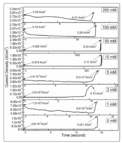
Fig. 1. Typical current density vs. time curves for the ECM of tin in 200-μm-thick electrolyte layers containing various concentrations of nitrate and 1 mM Cl- at bias voltage 5 V.
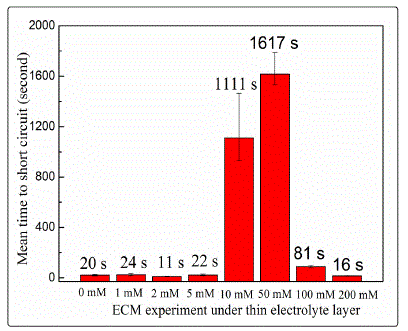
Fig. 2. Effect of nitrate concentration on the mean time to short circuit of two tin electrodes in 200-μm-thick electrolyte layers at bias voltage 5 V
In situ real-time observation of ECM development
Figs. 3 and 4 show in situ optical micrographs of the ECM
of tin in 200 μm-thick electrolyte layers containing 1 mM Cl-
and different nitrate concentrations at 5 V at different time
points. The amounts of precipitates and bubbles increased
with increasing nitrate concentration at the initial time. A thick
precipitate layer formed near the anode side rather than the
area between the anode and the cathode at the end of ECM.
This result can be attributed to the much faster migration rate
of OH- than those of Sn4+ and Sn2+ caused by the strong
convection effect resulting from bubbles escaping from the
cathode [22]. As shown in Figs. 4a-4d, the number of tree- or
needle-like dendrites increased with increasing nitrate
concentrations.
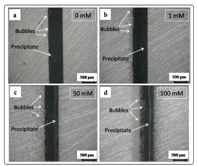
Fig. 3. In situ optical micrographs of electrochemical migration of tin in 200-μm-thick electrolyte layer containing 1 mM Cl- and varied nitrate concentrations with bias voltage of 5 V at 2 s: (a) 0 mM, (b) 1 mM, (c) 50 mM, (d) 100 mM (anode is on the right and cathode is on the left).
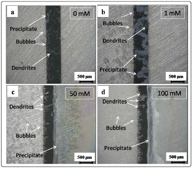
Fig. 4 In situ optical micrographs of electrochemical migration of tin in 200-μm-thick electrolyte layer containing 1 mM Cl- and varied nitrate concentrations with bias voltage of 5 V within different time intervals: (a) 0 mM, 20 s; (b) 1 mM, 24 s; (c) 50 mM, 1617 s; (d) 100 mM, 81 s (anode is on the right and cathode is on the left).
Real-time pH distribution on the electrode surface during ECM
Local pH development was visualized by adding a universal
pH indicator (pH 1-14) to the 200 μm-thick electrolyte layer to
understand the local pH distribution on both electrodes during
the ECM test. Fig. 5 shows the in situ visual evidence of the pH
distribution change with time in 1 mM Cl- and varied nitrate
concentrations at 5 V. Prior to applying bias voltage, the pH was
between 6 and 7. Upon voltage application, the electrolyte on
the cathode part turned alkaline (blue/purple in color), whereas
that on the anode part became acidic (red in color) within 2 s.
The pH of the cathode area increased with time, whereas that
of the anode area decreased with time. The amount of bubbles
increased on the cathode side, and change in pH became faster
as the nitrate concentration was increased. The alkaline region
(blue/purple in color) diffused quickly to the anode side with
time because of the increasing OH- concentration and strong
convection effect caused by the evacuation of bubbles on the
cathode surface. Furthermore, the alkaline region diffused
faster in 50 mM than 200 mM nitrate in 10 s. This finding could
be attributed to the hindering effect of the thicker precipitate
layer in 200 mM nitrate, which slowed the migration of OH-.
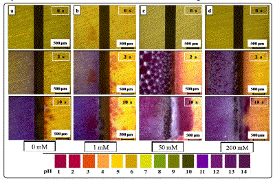
Fig. 5. Visualization of localized pH distribution on the both electrodes using pH indicator in 200-μm-thick electrolyte layers containing 1 mM Cl- and varied concentrations of nitrate ion at 5 V within different time intervals (anode is on the right and cathode is on the left).
Ex situ characterization of dendrites and precipitates
The microstructure and composition of the products
generated after ECM were characterized using SEM, EDS, and
XRD. Fig. 6 shows the SEM images of the samples after ECM
tests with various nitrate concentrations at 5 V. Tree- and
needle-like dendrites formed after all the ECM tests, but the
branches of the dendrites became coarser in the presence of
various nitrate concentrations. The composition of products
generated after ECM was determined by EDS and XRD. Fig. 7a
shows the typical XRD peaks of Sn, SnO, and SnO2, and the
blunt peak is attributed to the peak of epoxy resin base.
Therefore, the products generated from the ECM test were
mainly composed of stannic hydroxide/oxide and stannous
hydroxide/oxide. Moreover, the EDS data of the dendrites
produced after ECM in the presence of 100 mM nitrate at 5 V
for 81 s is shown in Fig. 7b. The dendrites consisted mainly of
tin, which agrees with the results of a previous study [20].
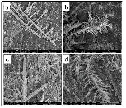
Fig. 6. SEM images of dendrites formed during the ECM of tin in 200-μm-thick electrolyte layers containing 1 mM Cl- and varied concentrations of nitrate ion at 5 V within different time intervals: (a) 0 mM, 20 s; (b) 1 mM, 24 s; (c) 50 mM, 1617 s; (d) 100 mM, 81 s (obtained between the two electrodes).
Discussion
Basic reactions involved in the ECM of tin
According to our previous work [16,21], the main anodic
reactions for tin in TELs containing 1 mM Cl- are as follows:

Before the generation of dendrites, the main cathodic reactions may only include the reduction of water (Reaction (5))

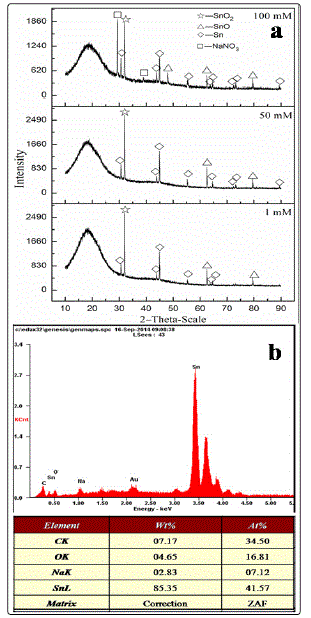
Fig. 7. Composition analysis of (a) XRD peaks of products formed during the ECM in 200-μm-thick electrolyte layers containing 1 mM Cl- and varied nitrate concentrations and (b) EDS pattern of dendrites formed during the ECM of tin in 200-μm-thick electrolyte layers containing 1 mM Cl- and 100 mM nitrate ion at 5 V for 81 s.
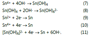
When these ions come in contact during the migration, the dominant precipitate Sn(OH)4 will be formed easily because of its low solubility (solubility product constant Ksp = 10-56, at 298.15 K) as shown in Reaction (7). Sn(OH)4 will be dissolved to form [Sn(OH)6]2- under high OH- concentrations (Reaction (8)). The growth of dendrites can be attributed to the reduction of Sn2+, Sn4+, and/or [Sn(OH)6]2- .
Effect of nitrate ion on the ECM behavior of tin
I. Katsounaros et al. [28] found that electrochemical
reduction of nitrate ion might occur on tin electrode at high
cathodic potentials. However, the mechanism of nitrate
reduction is complicated because of its multi-electron nature
and the presence of a large number of intermediates [29, 30].
Nitrogen and/or ammonium are the main reaction products
in alkaline medium [31,32]. A consecutive reaction mechanism
can describe the reduction process as Reactions (12)-(14) [28,33]:

After the ECM test, the electrolyte was analyzed with
through ion chromatography (Metrohm 881 Compact IC Pro,
Switzerland). The electrolyte contained 12.62 mM ammonium
in the presence of 200 mM nitrate at a bias voltage of 5 V after
16 s. Nitrogen may be the main product in the test condition.
Tucker et al. [34] reported that nitrogen is main reaction
product of nitrate reduction on activated rhodium electrode
in alkaline solution.
Moreover, CV measurement was performed to account
for the effect of nitrate on the ECM of tin. Fig. 8 shows cyclic
voltammograms of Sn electrode in solutions containing 1 mM
NaCl and various nitrate concentrations. The peaks were
attributed to the oxidation/reduction of Sn2+ to Sn4+ (SnO2
and/or Sn(OH)4) species. The increase of the peak current in
the presence of nitrate is attributed to the increased corrosion
of tin because nitrate ion can be reduced to facilitate the
cathodic reaction [35]. However, whether the increase in
current density was mainly due to the nitrate reduction
reaction or the hydrogen evolution reaction that was
enhanced by the increase in ionic intensity remains to be
clarified. Thus, CV measurement was carried out in solutions
containing the same concentrations of nitrate and sulfate (Fig.
9). An increase in the current density from -1.6 V was observed
for the two solutions, and the current density of nitrite was
much higher than that of sulfate at any potential. The
conductivity of sulfate solution (13.48 mS/cm) was higher
than that of nitrate solution (8.79 mS/cm) at the same
concentration. These results prove that nitrate reduction plays
an important role during ECM and that it causes the sharp
increase in OH- amount with increasing nitrate concentration
(Reactions (12)-(14)). Furthermore, the peak current
corresponding to the oxidation/reduction of Sn2+ to Sn4+ in
the case of nitrate was much higher than that of sulfate. This
observation may be attributed to the fact that nitrate is more
aggressive than sulfate [36,37].
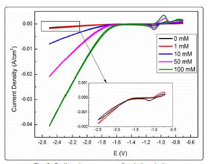
Fig. 8. Cyclic voltammograms for tin in solutions containing 1 mM Cl- and varied concentrations of nitrate (0 mM, 1 mM, 10 mM, 50 mM, 100 mM).
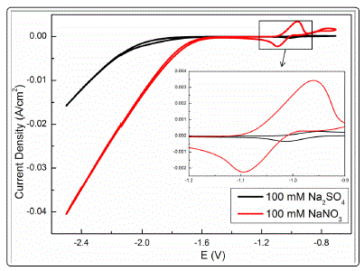
Fig. 9. Cyclic voltammograms for tin in solutions containing 1 mM Cl- and same concentration of nitrate and sulfate .
Effect of nitrate concentration on the ECM of tin
As aforementioned result of the mean time to short circuit
as a function of nitrate concentration (Fig. 2), the effect of
nitrate concentration on the ECM of tin is significant.
Therefore, the ECM dependence of tin throughout the whole
test nitrate concentration range was discussed.
At low nitrate concentration (1-5 mM) levels, the anodic
dissolution and cathodic deposition were accelerated mainly
because of the increment of ionic conductivity. The amount of
bubbles and precipitates increased compared with the
absence of nitrate. A loose precipitate layer occurred between
the anode and the cathode (Figs. 3 and 4). However, the loose
precipitate layer could not hinder the growth of dendrites
effectively.
With the increase in nitrate concentration from 10 mM to
50 mM, both the anodic and cathodic reactions were
considerably promoted at the beginning of the ECM, which
was demonstrated by the high current density and the increase
of bubbles evacuating from the cathode. A large amount of
precipitates formed between the anode and the cathode with increasing OH- and Sn4+ concentrations. However, under this
condition, dissolution of precipitates still cannot proceed
because a higher pH is required. The precipitates gradually
accumulated to form a thick precipitate layer. Fig. 10a shows
the 3D micrograph of the electrode system during the ECM in
a 200 μm-thick electrolyte layer containing 50 mM nitrate ion
and 1 mM Cl- at 5 V for 1617 s. The accumulated precipitates
with a height of 625 μm formed on the anode side and served
as a wall-like barrier to impede the migration of ions. However,
the accumulation of OH- produced by the cathodic reactions
caused Sn(OH)4 to disproportionate into [Sn(OH)6]2- (Reaction
(11)) and dendrites to grow.
When the nitrate concentration was further increased
(100-200 mM), a wall-like barrier also formed on the anode
side (Fig. 10b) and hindered the migration of ions. However,
sufficient OH- could be produced rapidly at the cathode
because of the extensive reduction of nitrate. In this case,
Sn(OH)4 dissolved to form [Sn(OH)6]2-, and the hindering
effect of the precipitate layer was weakened. Thus, dendrites
grew quickly toward the anode direction.
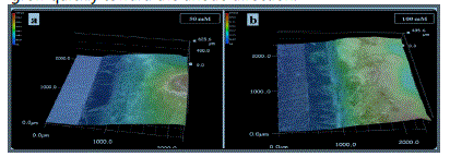
Fig. 10. 3D micrographs of precipitates formed during the ECM of tin in 200-μm-thick electrolyte layer containing 1 mM Cl- and varied nitrate concentrations at 5 V for different time intervals: (a) 50 mM, 1617 s; (b) 100 mM, 81 s (anode is on the right and cathode is on the left).
Conclusion
This study investigated the effect of nitrate concentration on the ECM of tin in TELs. At low nitrate concentrations (1-5 mM), the rate of dendrite growth did not change considerably. However, at intermediate nitrate concentrations (10-50 mM), dendrites grew at the slowest rate resulting from the accumulation of precipitates that acted as a wall-like barrier to hinder the migration of ions. At a high nitrate concentration (100 mM), the intensive cathodic reactions produced large amounts of OH-, which caused the dissolution of the precipitate layer and the fast growth of dendrites from the cathode to the anode.
Acknowledgements
The authors thank the National Natural Science
Foundation of China (Nos. 51571098) for their financial
support and the Analysis Support of the Analytical and Testing
Center, Huazhong University of Science and Technology.
Conflicts of Interest: The author reports no conflict of interest.
References
- Daniel M, Jellesen MS, Møller P, Ambat R. On the electrochemical migration mechanism of tin in electronics. Corros Sci. 2011;53:3366- 3379. https://dx.doi.org/10.1016/j.corsci.2011.06.015
- Jung JY, Lee SB, Joo YC, Lee HY, Park YB. Anodic dissolution characteristics and electrochemical migration lifetimes of Sn solder in NaCl and Na 2 SO 4 solutions. Microelectron Eng. 2008;85:1597-1602. https://dx.doi. org/10.1016/j.mee.2008.03.015
- Zhou Y, Huo Y. The comparison of electrochemical migration mechanism between electroless silver plating and silver electroplating. J. Mater. Sci. - Mater. Electron. 2016; 27:931-941. doi: 10.1007/s10854-015-3836-z
- Noh BI, Jung SB. Characteristics of environmental factor for electrochemical migration on printed circuit board. J. Mater. Sci. - Mater. Electron. 2008;19:952-956. doi: 10.1007/s10854-007-9421-3
- Lopez BG,Valdez SB, Zlatev KR, Flores PJ, Carrillo BM, Schorr WM. Corrosion of metals at indoor conditions in the electronics manufacturing industry. Anti-Corros. Methods Mater. 2007; 54:354-359. https://dx.doi. org/10.1108/00035590710833510
- Shnawah DA, Sabri MFM, Badruddin IA. A review on thermal cycling and drop impact reliability of SAC solder joint in portable electronic products. Microelectron. Reliab. 2012;52:90-99. https://dx.doi.org/10.1016/j. microrel.2011.07.093
- Medgyes B, Illés B, Berényi R, Harsányi G. In situ optical inspection of electrochemical migration during THB tests. J. Mater. Sci. - Mater. Electron. 2011;22:694-700. doi: 10.1007/s10854-010-0198-4
- Lee SB, Yoo YR, Jung JY, Park YB, Kim YS, Joo YC. Electrochemical migration characteristics of eutectic SnPb solder alloy in printed circuit board. Thin Solid Films. 2006;504:294-297. https://dx.doi.org/10.1016/j. tsf.2005.09.022
- Medgyes B, Illés B, Harsányi G. Electrochemical migration behaviour of Cu, Sn, Ag and Sn63/Pb37. J. Mater. Sci. - Mater. Electron. 2012;23:551- 556. doi: 10.1007/s10854-011-0435-5
- Yu DQ, Jillek W, Schmitt E. Electrochemical migration of lead free solder joints. J. Mater. Sci. - Mater. Electron. 2006;17:229-241. doi: 10.1007/ s10854-006-6765-z
- Noh BI, Jung SB. Behaviour of electrochemical migration with solder alloys on printed circuit boards (PCBs). Circuit World. 2008;34:8-13. https://dx.doi.org/10.1108/03056120810918060
- He X, Azarian MH, Pecht MG. Evaluation of electrochemical migration on printed circuit boards with lead-free and tin-lead solder. J. Electron. Mater. 2011;40:1921-1936. doi: 10.1007/s11664-011-1672-3
- Noh BI, Lee JB, Jung SB. Effect of surface finish material on printed circuit board for electrochemical migration. Microelectron. Reliab. 2008;48:652- 656. https://dx.doi.org/10.1016/j.microrel.2007.09.006
- Minzari D, Jellesen MS, Møller P, Wahlberg P, Ambat R. Electrochemical migration on electronic chip resistors in chloride environments. IEEE Trans. Device Mater. Reliab. 2009;9:392-402. doi: 10.1109/TDMR.2009.2022631
- Verdingovas V, Jellesen MS, Ambat R. Influence of sodium chloride and weak organic acids (flux residues) on electrochemical migration of tin on surface mount chip components. Corrosion Engineering, Science and Technology. 2013;48:426-435. doi: https://dx.doi.org/10.1179/174327821 3Y.0000000078
- Zhong X, Guo X, Qiu Y, Chen Z, Zhang G. In Situ Study the Electrochemical Migration of Tin under Unipolar Square Wave Electric Field. J. Electrochem. Soc. 2013;160: D495-D500. doi: 10.1149/2.014311jes
- Verdingovas V, Jellesen MS, Ambat R. Effect of pulsed voltage on electrochemical migration of tin in electronics. J Mater Scie: Mater in Electron. 2015;26:7997-8007. doi: 10.1007/s10854-015-3454-9
- Dominkovics C, Harsányi G. Fractal description of dendrite growth during electrochemical migration. Period Polytec Elec Eng. 2008;52:13- 19. doi: 10.3311/pp.ee.2008-1-2.02
- Dominkovics C, Harsányi G. Fractal description of dendrite growth during electrochemical migration. Microelectron. Reliab. 2008;48:1628- 1634. doi: https://dx.doi.org/10.1016/j.microrel.2008.06.010
- Minzari D, Grumsen FB, Jellesen MS, Møller P, Ambat R. Electrochemical migration of tin in electronics and microstructure of the dendrites. Corros Sci. 2011;53:1659-1669. doi: https://dx.doi.org/10.1016/j. corsci.2011.01.009
- Zhong X, Zhang G, Qiu Y, Chen Z, Zou W, Guo X. In situ study the dependence of electrochemical migration of tin on chloride. Electrochem. Commun. 2013;27:63-68. https://dx.doi.org/10.1016/j. elecom.2012.11.010
- Zhong X, Zhang G, Qiu Y, Chen Z, Guo X. Electrochemical migration of tin in thin electrolyte layer containing chloride ions. Corros Sci. 2013;74:71-82. https://dx.doi.org/10.1016/j.corsci.2013.04.015
- Lacasa E, Canizares P, Llanos J, Rodrigo MA. Effect of the cathode material on the removal of nitrates by electrolysis in non-chloride media. J hazard mater. 2012;213:478-484. https://dx.doi.org/10.1016/j. jhazmat.2012.02.034
- Liu GD, Wu WL, Zhang J. Regional differentiation of non-point source pollution of agriculture-derived nitrate nitrogen in groundwater in northern China. Agr ecosys environ. 2005;107:211-220. https://dx.doi. org/10.1016/j.agee.2004.11.010
- Wu S, Wang B, Yang D, Wei H, Li H, Pan L, et al. Ambient particulate air pollution and circulating antioxidant enzymes: A repeated-measure study in healthy adults in Beijing, China. Environ. Pollut. 2016;208:16-24. doi: 10.1016/j.envpol.2015.06.002
- Camargo JA, Alonso A. Ecological and toxicological effects of inorganic nitrogen pollution in aquatic ecosystems: a global assessment. Environ. Int. 2006;32:831-849. doi: 10.1016/j.envint.2006.05.002
- Medgyes B, Zhong X, Harsányi G. The effect of chloride ion concentration on electrochemical migration of copper. J Mater Scie: Mater in Electron. 2015;26:2010-2015. doi: 10.1007/s10854-014-2640-5
- Katsounaros I, Ipsakis D, Polatides C, Kyriacou G. Efficient electrochemical reduction of nitrate to nitrogen on tin cathode at very high cathodic potentials. Electrochim. Acta. 2006;52:1329-1338. doi: https://dx.doi. org/10.1016/j.electacta.2006.07.034
- Ambrosioni B, Barthelemy A, Bejan D, Bunce NJ. Electrochemical reduction of aqueous nitrate ion at tin cathodes. Can. J. Chem. 2013;92:228-233. doi: 10.1139/cjc-2013-0406
- Katsounaros I, Kyriacou G. Influence of nitrate concentration on its electrochemical reduction on tin cathode: Identification of reaction intermediates. Electrochim. Acta. 2008;53:5477-5484. doi: https://dx.doi. org/10.1016/j.electacta.2008.03.018
- Badea GE. Electrocatalytic reduction of nitrate on copper electrode in alkaline solution. Electrochim. Acta. 2009;54:996-1001. doi: https://dx.doi. org/10.1016/j.electacta.2008.08.003
- De D, Kalu EE, Tarjan PP, Englehardt JD. Kinetic Studies of the Electrochemical Treatment of Nitrate and Nitrite Ions on Iridium - Modified Carbon Fiber Electrodes. Chem eng technol. 2004;27:56-64. doi: 10.1002/ceat.200401832
- Bockris JM, Kim J. Electrochemical treatment of low-level nuclear wastes. J. Appl. Electrochem 27 (1997) 623-634. doi: 10.1023/A:1018419316870
- Tucker PM, Waite MJ, Hayden BE. Electrocatalytic reduction of nitrate on activated rhodium electrode surfaces. J. Appl. Electrochem. 2004;34:781- 796. doi: 10.1023/B:JACH.0000035607.19248.b6
- Refaey S, El Rehim SA. Inhibition of chloride pitting corrosion of tin in alkaline and near neutral medium by some inorganic anions. Electrochim. Acta.1997;42:667-674. doi: 10.1016/S0013-4686(96)00212-5
- Rehim SA, Sayyah S, El Deeb M. Corrosion of tin in citric acid solution and the effect of some inorganic anions. Mater. Chem. Phys. 2003;80:696- 703. doi: https://dx.doi.org/10.1016/S0254-0584(03)00128-7
- Sasaki T, Kanagawa R, Ohtsuka T, Miura K. Corrosion products of tin in humid air containing sulfur dioxide and nitrogen dioxide at room temperature. Corros Sci. 2003;45:847-854. doi: https://dx.doi.org/10.1016/ S0010-938X(02)00151-8
