Research Article
Research Article
Preliminary Design and Computational Fluid Dynamic analysis of Flapping Wing of Micro Aerial Vehicle for Low Reynolds Numbers Regime
1Department of Mechanical Engineering, Clemson University, Clemson, SC, USA
2Army Research Laboratory, Aberdeen, MD, USA
*Corresponding author: Abduljaleel Altememe, Department of Mechanical Engineering, Clemson University, Clemson, USA, E-mail: aalteme@clemson.edu
Received: March 19, 2019 Accepted: April 29, 2019 Published: May 9, 2019
Citation: Altememe A, Myers OJ, Hall A. Preliminary Design and Computational Fluid Dynamic analysis of Flapping Wing of Micro Aerial Vehicle for Low Reynolds Numbers Regime. Int J Aeronaut Aerosp Eng. 2019; 1(2): 36-45. doi: 10.18689/ijae-1000106
Copyright: © 2019 The Author(s). This work is licensed under a Creative Commons Attribution 4.0 International License, which permits unrestricted use, distribution, and reproduction in any medium, provided the original work is properly cited.
Abstract
This research describes the investigation of the behavior of the flow over a 2D Flapping airfoil for flapping wing of Micro Aerial Vehicles (FWMAV) at very low Reynolds number regieme. The behavior of the flow wake at the trailing edge is studied by the analysis of streamlines for each incidence angle and results are compared by the study of two different flapping airfoils at two different fluids. The use of Fluid Structure Interaction (FSI) simulation has shown accuracy in predicting lift and drag forces at different angles of attack for upstroke and down stroke. This work simulates a classical flow pattern (Von Karman Street) that can form as fluid flows past a flapping NACA0012 airfoil, and S1223 airfoil at low Reynolds numbers and low velocities. These two airfoils have been selected and investigated by using basic computational fluid dynamics and fluid structure interaction modules. The S1223 airfoil, designed by University of Illinois at Urbana and the NACA0012 airfoil were selected for their high lift characteristics at low Reynolds number regime. Simulations were also conducted to check the lift and drag forces for both airfoils at low Reynolds number regime. Velocity distributions were analyzed at different angles of attack for these airfoils. The magnitude and the frequencies of the oscillation generated by the fluid around the airfoils were computed and compared between the airfoils.
Keywords: Preliminary Design; Dynamic Analysis; Reynolds Numbers; Flapping Wing.
Nomenclature: u: velocity field, m/sec; ufluid: Fluid velocity, m/sec; ufluid: Fluid velocity component in x direction, m/sec; vfluid: Fluid velocity component in y direction, m/sec; usolid: Displacement field, mm; usolid: Displacement field component in x direction, mm; vsolid: Displacement field component in y direction, mm; p: Pressure, N/m2; ρ: density of the fluid, Kg/m3; F: volume force vector, N; T: absolute temperature, K; μ: dynamic viscosity, Pa.s; I: denotes the unit diagonal matrix; Re: Reynolds number; L: Length of channel, m; H: Height of channel, m; c: Airfoil chord length, m; t: Time, sec; x: complex coordinates for the horizontal; y: complex coordinates for the vertical; z: every point in the cylinder plane; ζ: every point in the airfoil plane.
Introduction
One of the main goals of Micro Air Vehicles (MAV) development is to reduce the risks and time that needed to collect the data in combat and reconnaissance situations. Miliary combat operations have placed a high premium on reconnaissance for Unmanned Aerial Vehicles (UAVs) and Micro Air Vehicles (MAVs). UAVs and MAVs provide circumstantial awareness that will shape the decisions of the squad command, such that these platforms are designed to be the eyes and ears for the war fighter. One approach for accomplishing this mission is to develop a biologically inspired Flapping Wing MAV (FWMAV) that can maneuver into confined areas and possess potential hovering capabilities. This platform can potentially be equipped with microphones, cameras, and gas detectors, but the development to construct Micro Air Vehicles (MAV) that can fly at low Reynolds number aero dynamics is big challenge.
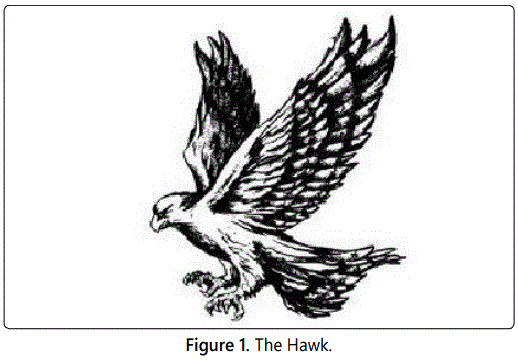
The propulsion through flapping of wings has long been a compelling subject for bio-inspired and bio mimicry research. This has become true, particularly with the advent and desire to create systems that mimic bird-flight in the Micro Aerial Vehicle (MAV) community. One crucial step is the analysis and design of airfoil that will produce minimum drag with maximum lift. Therefore, flapping airfoils are crucial for better aerodynamic performance. Flapping wing design replicates the primary mode of flight propulsion in the animal kingdom [1]. For example, birds such as the hawk shown on figure 1, have mastered the art of wing flapping.
The theories concerning how the typical lifting surface oscillates to produce both lift and propulsion are classified in unstable aerodynamics. Conversely, the unsteady effects can be also related to aero elastic effects, where mutual interaction between aerodynamics and elastic forces on lifting surfaces is investigated. The aero elastic effects are observable since the first attempts of flight, being the cause of many unsuccessful flights, beginning in the 1920s. At the time, the primarily purpose was to gain an understanding of aero elasticity. The first model to linearize the aero elastic effects was based on small disturbance theory [2]. This topic was explored as a means of understanding how birds can achieve flight [3,4]. This work is also of interest to groups studying the geometrical horizons of ornithopters [5]. While much progress is been made in understanding the basic mechanisms involved in propulsive flapping, practical flapping ornithopters have not been developed for various reasons. The most obvious of these is the severe mechanical challenge associated with building a flapping wing. Even if this challenge is overcome, the efficiency afforded by propellers (the obvious choice for low-speed propulsion) has not been improved upon by oscillating airfoils in any theoretical or experimental study.
As generally known, birds flap their wings in order to harness thrust when flying. When a bird changes the position of its wings, it forms an angle of attack that creates the lift force. In contrast, an aircraft harnesses power from the engine for thrust, and the angle of attack is formed by the flap/aileron shape to provide for the lift. During landing, a bird changes the position of its wings for drag, whilst its tail that acts as a rudder to maneuver and decreases its mid-air speed. On the other hand, an aircraft changes the positioning of landing flap on its wing to increase drag thus decreasing the thrust. The aircraft tail is used as to maneuver and to provide for stability [6,7]. So, the tail end structure is a vital part for landing, and this is similar with how a bird uses its tail to decrease its speed [8].
Wing flexibility can profoundly affect the flight performance of natural [9] and engineered systems. For example, through an experimental study of the hawkmoth or Manducasexta, (commonly known as the Carolina sphinx moth) [10] showed that a flexible wing was able to generate more lift-favorable momentum flux than a stiff wing. In addition, Barannyk et al. [11] showed that flexible airfoils outperformed rigid airfoils. In addition, further studies have shown that flight performance can be optimized at certain levels of flexibility, beyond which flight forces and/or efficiency decrease [9].
The fluttering flight of insects, birds, and bats has been the focus of numerous researchers in different fields, including biology, zoology, aerodynamics, optimal design, and electronics. This is because birds and insects are exceptionally proficient; fly with high maneuverability; and benefit aerodynamically especially in low Reynolds numbers flight regime. For a long time, numerous efforts have been made to mimic natureʼs fliers in order to make simulated fluttering/flapping wing vehicles. It is of note that the majority of the early trials for “flying machines” adopted flapping mechanisms for generating thrust and/or lift [3]. For example, in 9th century, Muslim Spain, more than a thousand years ago, on a hill in Cordoba, Abbas bin Firnas, the Father of the Flying Machine boldly set out to do what no man had done before. He was set to test the first flying machine in recorded history. He constructed wings with a span estimated between four and five meters. Striving to keep the flying machine strong and light enough, he manufactured a light wooden frame, assumed to be bamboo, which is hollow like the bones in a birdʼs wing [12].
Gliding without engine was successfully further expanded by the Wright brothers until their invention of engine powered aircraft flew 260 meters. The Wright brothers are well known today for their first attempt to fly on 1st December 1903. Since then, they have gained fame and the field of aviation has been developing rapidly with the integration of engine to the aircraft. The Wright Brotherʼs key to their success is by studying how birds fly similar to what Ibn Firnas had done 1,000 years ago. Wright realized that a bird maintains its stability mid-air or when veering left or right by changing the positioning of its wings. Prior to building the aircraft, the Wright brothers used gliders in order to avoid any mishaps. They invented a kite with a similar function in order to confirm the effectiveness of the method [13].
In 1997 the Wide Area Surveillance Projectile (WASP) project was commenced as a cooperative venture between Massachusetts Institute of Technology (MIT) and the Charles Stark Draper Laboratories. The focus was to improve the structural design and manufacturing of components capable of surviving launch at lightweight and remaining as durable as possible. Composite materials were the principal materials used in manufacturing [4]. Calogero J et al. conducted a design and optimization analysis of a new contact aided compliant mechanism. The mechanism facilitated was end and sweep compliant motion by using an angled joint. The optimization is solved by using NSGA-II a genetic algorithm. In order to achieve a bio-inspired wing gait called continuous vortex gait, the wings of the UAV need to bend and sweep simultaneously. So, this can be achieved by inserting the bend and sweep compliant mechanism into the leading edge wing of the UAV [14].
Researchers have tried to study the planning mechanism of animals and utilize bio-inspired approach in trajectory generation. The bio-inspired general “tau theory” has received great interest. This theory was developed from the action planning mechanism of animals based on tau theory, three Intrinsic Tau Guidance Strategies (ITGSs) are studied for perching tasks like a bird [15].
Design and optimization of compliant spine (CS) [16], a multi-objective optimization problem with three objectives is formulated in order to perform the design optimization of the compliant spine. The goal of the optimization is to minimize the peak stress and mass while maximizing the deflection, subject to geometric and other constraints. The authors used a flapping wing UAV to test the accuracy of the design optimization procedure and prove the effectiveness of compliant spine design. The results from flight test proved the ability of the compliant spine to produce an asymmetry in the UAV wing kinematics during the up and down strokes.
For the wake structure, Wagner [17] published a way to calculate the distribution of vorticity in the wake structure of an airfoil undergoing unsteady motions. After that, Von Karmin used Kelvin circulation theory and a wake integral approach to find the lift and thrust developed by a flapping airfoil [18]. Also, Theodorsen [2] analyzed the problem by potential flow theory and solved the wake integral with Bessel functions, hence adding great mathematical complexity. Also, his work was focused with lift forces and applied to the flutter problem. Hall et al. [5] studied the issue of minimum power flapping flight and compute the optimal flapping frequency by using a vortex-lattice model of the wake.
With such variety of relevant research, there is still an opportunity to begin to develop flapping wing unmanned aerial systems that truly replicate birds. This can begin by further simulating the flapping mechanism of cm-scal birds. The purpose of this study is to model the flapping or pitching motion of two different airfoils at two different fluids and evaluate the capabilities of fluid structure interaction model on modelling unsteady pitching flows, which is an approximation of the oscillation or vibration that can be faced by aerodynamic bodies during flight at very low Reynolds numbers regime. The two-dimensional CFD computations here presented are based on the proposed studies from Turek et al. [19] at very low Reynolds number laminar flow.
Selection of airfoils for better design of aerodynamic and aerodynamic performance is very important such as aircraft and wind turbine and likewise for the preliminary design of a flapping wing UAV. The proposed flapping wing UAV will require efficient operation of airfoils in low Reynolds number, particularly for micro and cm-scale unmanned aerial vehicles. The research approach is based on applying force at trailing edge of the airfoil to produce flapping airfoil at low Reynolds number laminar flow regime. By implement fluid structure instruction (FSI), the flow pattern of the von Karman vortex street can form as fluid flows past a flapping airfoil structure. The analysis also helps in monitoring the vortices which may induce vibrations in the flapping airfoil. The proposed research expands previous studies on the response of simplistic systems involving a fluid-structure interaction where the large deformations affected the flow path. The results obtained from simulation have compared between the two airfoils. The magnitude and the frequencies of the oscillation generated by the fluid around the structure are computed and compared with the values proposed by other researchers in the established literature [19].
Flapping Wing Airfoil Design and Implementation
This section focuses on the modeling part of the research work. First, an overview of the strategy used for airfoil geometry, then, using solid modeling to build the MAV body frame and particularly the flapping wing frame, then baseline finite element static analysis and laminar flow analysis around the flapping wing in the designs. Since the proposed flapping wing UAV is bio-inspired, one hypothesis is that the best design for wings should replicate real birds. The foundation of this overall research investigates possible designs that vary the dimensions, the body and wings that could be designed to replicate different birds. This research must also focus on the ratio of body length to wing length as well as weight. As a baseline the FWMAV is modeled after the Warbler bird.
Design Concepts
The proposed mechanical design makes use of previously encountered studies involving aerodynamics of small vehicles. The small length scales and low speeds that the UAV will travel are modeled using laminar potential flows. The mechanical design is conducted in Solid works before being analyzed further in COMSOL. The fundamental Navier-Stokes equations are used to give a complete description of all possible flow situations. However, obtaining a numerical solution using the Navier-Stokes equations is time consuming, even for the case of a laminar flow field around a wing.
The first stage was to design a wing that utilized the lift capabilities of an airfoil. Initial benchmarking for the airfoil used the research by Pelletier and Mueller [20]. Pelletier and Mueller [20] were able to quantify the aerodynamics of low Reynolds number aerodynamic airfoils. The lift, drag and pitching moment coefficients, in addition to the endurance parameter, determine the flight parameters that are associated with the flight characteristics performance of low Reynolds numbered wings. The physical constraints of the model were designed as bird wings and were either flat bottom or featured a 4% camber. The wings had a thickness to chord ratio of .0193 and were selected for the ability to glide at low Reynolds number. Each wing that Pelletier and Mueller studied was divided into 2D models and semispan aspect ratios, a dimensionless expression for relative length of the wing [19,20].
Notable trends were that when higher semi-span aspect ratios having higher lift coefficients and pitching-moment coefficients while having relatively similar drag coefficients for angles of attack between 0 and 10 degrees. The Lift to drag ratio was highest for the higher aspect ratios as well demonstrating that longer wings will provide better aerodynamic properties. This observation was also consistent for the cambered wings that had higher lift coefficients despite also having higher drag ratios. The shape of the trailing edge was also examined as of whether a sharp trailing edge or elliptical trailing edge was better for performance. The only variable that was under the edge design was the pitching-moment coefficient, for the flat wings only. At an angle of attack of 0 degrees, there was a slight increase in positive pitching-moment from sharp trailing edges that was not well observed in the cambered models. For the purposes of gliding, the data shows that a cambered wing with a high semispan aspect ratio (i.e. large wing span with small chord length) will have the best performance [20].
Andro [21] mentioned the importance of the low aspect ratio by corroborating the work of Jacquin who examined the flapping frequencies influence on the aerodynamics. Frequencies of the airfoils were compared using the Stroudal number as the primary dimensionless parameter. The study was conducted using a NACA0012 airfoil at a Reynolds number of 1000 and the flow field was analyzed numerically to determine the behavior of the air around the wing. From the calculated force gradients, there were definite and visible differences in the distribution of the air as the wing flapped relating to vorticity of the air. The pressure gradients on the down stroke were much higher, but on the upstroke a vortex was present that reduced pressure throughout the entire upstroke [21].
Relevant numerical information included the use of Stroudal values within the range of a bird in flight. Those values were below St=0.5. Relevant calculations that were used to arrive at this value are all dependent on flight parameters that vary through time.
Kaplan, Altman et al. explored vorticity was an important factor to flight even with the benefit of gliding. Wing shape with low aspect ratios are for their aerodynamics are directly related to the wings while gliding. The selected shapes for analysis were a rectangle, elliptical and delta wing. The rectangular performed the best among the shapes in terms of generating the highest lift, but the delta wing had the strongest relative vortices. The movement of theses vortices changes the pressure gradient across the wings. The airfoils movement generally changes with the vortices and the lift that is calculated is subject to those same vortices. Combining these analyzes isolates three main design principles i) A thin cambered wing ii) the largest forces experienced on the down stroke and iii) a wing that compromised between a delta angle and a rectangular profile.
Based on the above, with significant contributions from the above research, an interative MATLAB R2014b program was used to perform airfoil design as shown in figure 2. Equations 1 & 2 were implement to x, y & z-coordiantes of the airfoil. The airfoil was designed using a standard Joukowski Transformation of a potential flow field using the equations shown below. Once the complex z was solved for, the x and y coordinates that corresponded to the airfoil were exported into Solid works using the Curves feature to create a workable sketch to generate an airfoil to use in the investigation.

Also, biological flapping wing flyers achieve flight maneuverability and efficiency in low speed flight regimes which have outperformed man-made flyers. The current Micro Aerial Vehicle (MAV) design goals are to develop flyers that maintain flight in regimes that biological flyers excel in low speeds, hovering (future research), and urban settings. This flight is characterized by flow phenomena that are not well understood such as, flow separation and vortical flow.
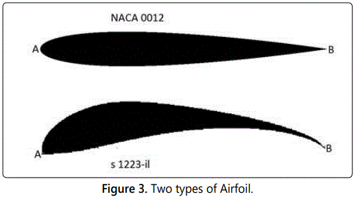
For the current study, two airfoils have been selected as shown in figure 3, S1223 airfoil designed in University of Illinois, Urbana Champaign and NACA0012 which is being used extensively for the wingtip in a lot of aerospace applications from the tiny Cessna to the giant C–5 Galaxy [22,23], and there is a strong base of historical data available to confirm the results of the CFD simulations. The Laminar Regime has been considered because the low Reynolds number flight regime is characterized by complex flow phenomena such as: viscous flow, transition from laminar flow to turbulence, flow separation, vertical flow, etc., as well as the proposed low velocity of the MAV. These flow phenomena are rarely experienced in high Reynolds number conventional fixed wing flight and have not been extensively studied. Due to the complexities of flapping flight aerodynamics, the aerodynamics is not well understood.

Fluid-Structure Interaction
The deformation of natural wings results from the interaction between forces imposed by the fluid surrounding the wing, the wings material properties (e.g. mass and stiffness distributions), and the actuation of the wing. When an animal, such as a bird, possesses intrinsic wing muscles, the forces due to flapping passively interact to produce the spatial and temporal patterns of wing movement and shape. Inertial forces result from the resistance of the wing to changes in its velocity; aerodynamic forces result from the fluid surrounding the wing; and elastic forces govern the deformation of the solid wing and connecting structure that is subject to these body and surface forces. The complex interactions between these aerodynamic and inertial/elastic forces essentially define the field of aero elasticity [24]. However, we do not yet have a clear understanding of the principles that govern the mechanical design of flexible wings for the dual role of efficient propulsion and inertial sensing. This issue is a primary motivation for the research undertaken here.
The coupling of the inertial/elastic forces with the aerodynamic forces can in some circumstances lead to an instability that can destroy the structure (e.g. flutter), much like the famous example of the Tacoma Narrows Bridge [24]. Thus, understanding the aero elastic nature of animal wings may not only inform the biological principles behind wing compliance but might also provide design criteria that can be applied to improve engineered systems. However, since birds have different wing flexibilities and actuation frequencies that depend on wing size and speed of flapping, it can be difficult to extract the biological principles that govern the use of flexible wings in the birdʼs flight.
In this paper we focus on fluid-structure interactions focuses on how the structural and fluid dynamics of and around a wing change with actuation frequency and airfoil flexibility. Through the development and analysis of a computational model of a two dimensional airfoil at laminar flow, we found that fluid forces do not dramatically change airfoils shape and thereby modify flight forces (i.e. the deformation in airfoil is dominated by the actuation of the airfoil structure, not the fluid loads imposed up on it).
So, considering the fluid flow around the airfoils to be compressible, the equations used by the solver are Navier Stokes equations as shown below:
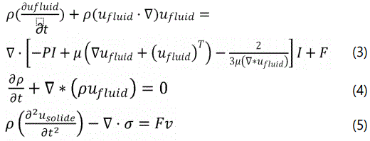
Where, the velocity field components ufluid=(ufluid,vfluid) and displacement field components usolid=(usolid,vsolid).
In general there is no a specific known analytical solution for the Navier–Stokes equations, but by using the vicinity of critical points in the flow to derive the local solutions [25]. In other hand, the flow is characterized by low Reynolds number [26] which is given by:

2D Simulation solution
To simulate the fluid structure interaction, the model requires a multi-physics capability for every step of the structure in the simulation [27,28]. The proposed fluid structure interaction FSI model was simplified to reduce the computational tax, so there are many assumptions must be made. Therefore, the model geometry contains the airfoil inside open domain [29] as in figure 4. For more detail see Turek and Hron [19].
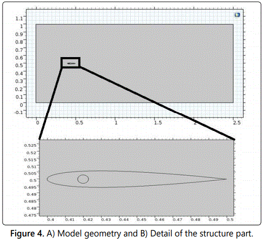
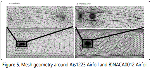
The dimension of open domain is (1 m height and 2.5 m long). The structure of flapping airfoil is composed of a fixed Roller (circular domain) inside the airfoil with 0.003 m radius and the center of the airfoil is located and shape centered at (0.42,0.5). The length of the airfoil chord is 0.1 m, both of airfoils and the roller made of elastic material as in figure 5.
To ensure the model convergence and to avoid singularities on the sharp trailing edge, the NACA0012 airfoil is marginally modified starting with its unique shape [30].

Additionally Equation 7 is used to create and subsequently modify the airfoils. The constants are fixed between x=0 and x=1.008930411365 and (c) is the chord length. For s1223 airfoil data files and equations 1, 2, and 7 are used to the rescale wing. The airflow entering the wind tunnel replicates a parabolic velocity profile in the left side with mean velocity of 5 mile/hr (2.235 m/s) and is assumed to be fully developed [31]. This requires increasing the distance between the flapping airfoil and the inlet condition to prevent the effect of inlet velocity condition on the flow pattern according to equations 8 & 9.

Use step function for a smooth increase in velocity profile in time Eq (2) become

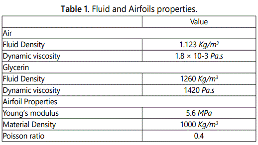
The outflow condition set up in right side of the tunnel with zero pressure because it is far away from the airfoil and there is no effect on the structure. Also, the model assumes there is no backflow in outflow to prevent the air from entering the domain through the boundary. Set no-slip condition on the upper side and lower side of the tunnel boundaries for the fluid. The properties of flapping airfoil and the air as in table 1.
2D Mesh Geometry
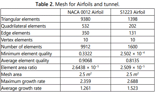
Meshing geometry is an essential part of the simulation process and can be crucial for obtaining the best results in the most efficient manner. After creating the model in COMSOL Multi physics, the mesh used in NACA0012 airfoil and s1223 airfoil is a Physics-controlled mesh. The far field required an extra coarse mesh element size. While close to the structure, the mesh is very refined to minimize singularities during the solver. The combined mesh generated is shown in figure 6. Lowering the minimum element size in mesh that is computationally taxing, the mesh for every airfoil and the tunnel is shown in table 2.
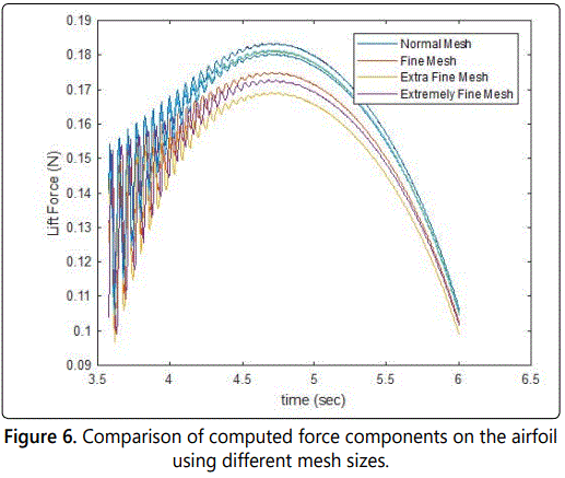
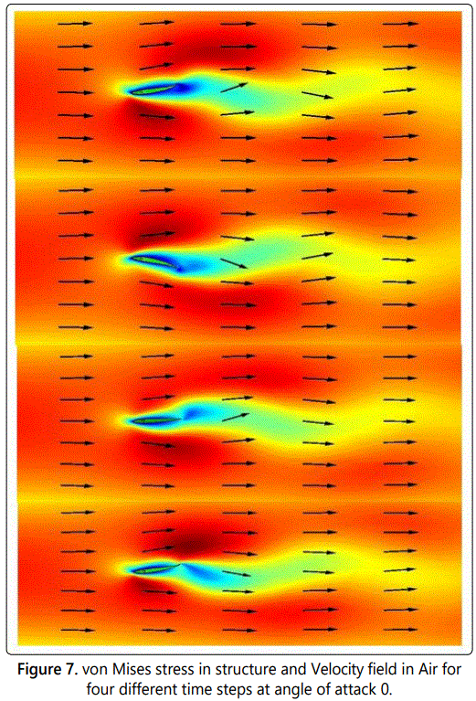
As shown in figure 7, for the structural analysis, the multi physics aspect of the problem and the desire to simultaneously solve the fluid and structure problem proved demanding, but COMSOLʼs fluid-structure interaction module handled these problems properly and efficiently with the default segregated solver settings, and minor modifications to the geometric multigrid solver. The fluid-structure module employs the previously mentioned Navier Stokes equations coupled with a solid stress-strain physics module. Additionally, COMSOLʼs free mesh utility was employed to capture the structural areas with more curvature and where the automatic mesh hierarchy could not be readily achieved. This was utilized to resolve specific mesh cases but computing times are significantly increased for the geometries. The comparison between mesh types generated by COMSOL Multi physics shows extra fine mesh best for Airfoil structure (Figure 6).
Results and Discussion for 2D Simulation
Velocity field
In the present analysis, the velocity field are analyzed at different angle of attacks (-2, 0, 2, 4, 6, 8, 10, 12, 14 and 16). Figure (7) shows the von Mises stress in the NACA0012 flapping airfoil and the velocity field for angle of attack 0 at four different times. From figure 7 notes that the fluid wake behind the airfoil induces a large oscillation in the solid protruding from trailing edge of airfoil. In other hand, the stagnation point obviously is seen on the leading edge because the flapping, the location of stagnation point change when the location of leading edge change. Also, in laminar flow there are separation and contact points but in this study, note that there is no separation point around the flapping airfoils because a laminar separation occurs closed to the leading edge which provokes a transition followed by a rapid turbulent reattachment, so, despite the relatively low Reynolds number, the flow is turbulent on the entire flapping airfoil. So, that mean the flow cover the airfoil and the von Karman vortex street past the airfoils, which will be essentially deformed and influences those stream field. The only separation point can clearly be seen in the trailing edge as shown in figure 7.
In additional we observed a vortex shedding around the trailing edge of both airfoils, in other hand pressure distribution around the flapping airfoil, max/min surface and total displacement at different time steps. The change in pressure around the flapping airfoil produces a force lift and drag. These forces evaluated by the difference between the upper surface pressure and the lower surface pressure. These results are very similar to the analyses conducted for biologically inspired UAVs from (44th AIAA Aerospace Sciences Meeting and Exhibit [31], Proceedings of SPIE, San Diego [3]).
Wake structure
The CFD results were used to visualize flow features. Results obtained at 5 mph at 0 angle of attack were qualitatively similar to those for (2,4,6,8,10,12,14 and 16). In Figure 7, a series of helicity contours are shown for each flap studied at 5 mph. Helicity values were analyzed from the instantaneous flow field forth elast time step computed in the CFD analysis. Planes within each of the four flap series were taken at 0 angle of attack along the air foil field, and were continue to be displayed behind to the trailing edge of airfoil. An angle of 0 degrees and small movement up and down represents the leading edge of the airfoil, while trailing edge represents the top and bottom of the airfoil, respectively. At this position, we observed a clockwise (as viewed from behind the airfoil) vortex coming off of the trailing edge of the airfoil, and a counter-clockwise vortex coming off of the leading edge of the airfoil on flow field.
Both vortices, once separated were seen to move in a downstream direction, being carried along by the surrounding axial flow. In figure 7, the flow field was moved forward to small degrees, closer to and above the leading edge of the airfoil. Again, a pair of counter rotating vortices was noted, coming off of the leading and trailing edges of the airfoil. These vortices were carried along with the forward flapping movements of the airfoil and were continually shed along the circumference of the airfoil as seen in figure 7. In order to develop an understanding of the evolution of these flow structures, streak lines were need to calculate for each of the angles attack simulated at 5 mph and for different wind speed.
Lift and drag forces
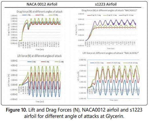
As shown in figure 8, the evolution of lift and drag forces for all time for both airfoils at 0-degree angle of attack, demonstrating the variation of the intensity pattern with time as the airfoil beats. Higher values indicate greater force loads, so peaks relate to apparent minimum size of the airfoil and troughs relate to when the airfoil appears at its maximum length. Airfoil beats do not include a perfect sinusoidal pattern, and the waveform contains both harmonics and noise. Glycerin as fluid used shows at t=1.5 sec NACA0012 airfoil the oscillation is fully developed but with s1223 airfoil at 1 sec. The variation of the lift and drag forces applied to the airfoils. So, in the Glycerin the average of the lift for s1223 airfoil is 2 N with oscillation magnitude of 320 N. In other hand the average of the drag force is about 130 N with an oscillation magnitude around 15 N.
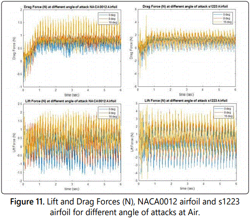
While the average of the lift for NACA0012 airfoil is 1.5 N with oscillation magnitude of 270 N. And, the average of the drag force is about 121 N with an oscillation magnitude around 6 N. The relatively good agreement between our results and Turki S, etc [32], lift and drag values suggests that the unsteady, laminar and incompressible 2D flow past an oscillated airfoil inside horizontal channel results. In figure 10 showing the fluid used is Air and the average of lift force in s1223 airfoil is 0.5 N and oscillation magnitude around 7 N while, the drag force is 1 N with oscillation 1 N but in NACA0012 airfoil the lift around 0.2 N with oscillation 2.6 N and the drag is 0.7 N with oscillation 0.5 N. Figures 9 and 10 show the drag force larger than lift force due to the viscosity of the fluid. In addition the oscillation in lift force is larger the oscillation in drag force because the oscillating in direction is larger than x-direction. The plot (figure 9) for Glycerin shows that for s1223 airfoil most of the lift is generated after one second of the motion, for NACA0012 airfoil most of the lift is generated after 1.5 sec but in figure 10 for NACA0012 most lift generated at one second and for s1223 airfoil less than one second. Also, when angle of attack increase both drag and lift force increase as shown in figures 11 and 12.
Forces validation
The shape of the lift and drag forces waves shown in figures 8 and 9 are also of interest. Primarily, even when unactuated there exists a distinct and somewhat unexpected flaps in leading edge. One would expect that for asymmetric aircraft, the lift and drag forces waves would be close to if not equal to zero for all angles of attack. But the trend observed in figures 8 and 9 demonstrate a quasi-parabolic yet asymmetric pitching response for flaps.
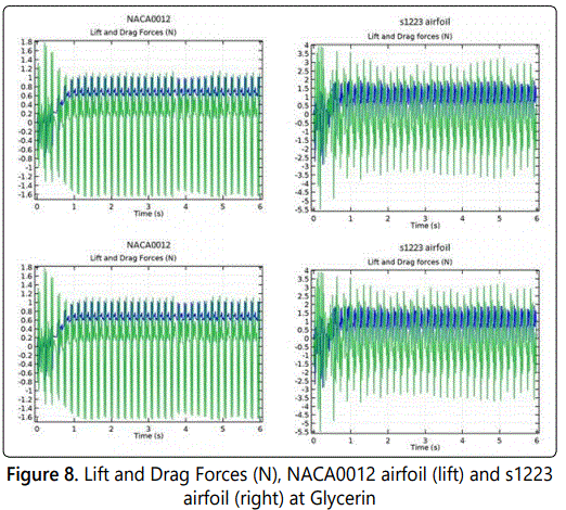
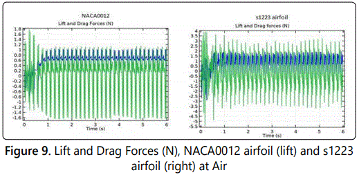
For the sake of this paper, only simulated flapping airfoil of the NACA0012 and s1223 airfoils are used at laminar flow for glycerin and air. The location of the fixed constrain was set to be the same in airfoils, however the mounting mechanism was not incorporated into the geometry, and thus the ensuing analysis strictly represents the aerodynamics of the airfoil of flapping wing for MAV alone. Going forward, only the trends of that analysis will be highlighted. Figures 10 and 11 shows the simulated pitch movement for lift and drag forces at glycerin and respectively. As noted in the glycerin data, the pitching move does indeed show a positive increase in the lift and drag forces when angle of attack increase.
However most notably, the challenge is that we have found very few literature articles or journal articles that address the cm scale but we can do is make an educated guess on travelation from micro to cm scale or from mm to cm scale.
Oscillation of trailing edge
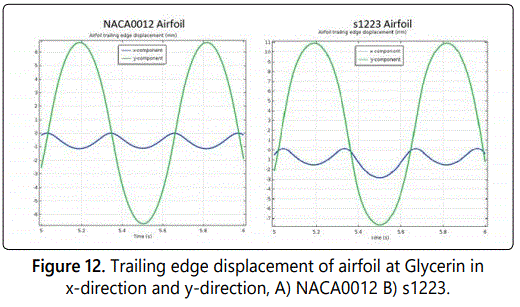
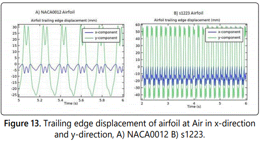
In figure 12 shows the oscillation magnitude of trailing edge for Glycerin driving fluid for both direction x and y. For NACA0012 the x-displacement oscillation about 1.0 mm around the average 0.5 mm and the difference in y displacement 0.5 mm with oscillation around 7 mm. The trailing edge oscillation in s1223 airfoil completely difference because the oscillation magnitude in x displacement around 1.5 mm with average -3 mm. Also, the difference in y displacement around 2 mm with oscillation magnitude of 9 mm. Figure 13 shows the oscillation magnitude of trailing edge by changing the fluid to Air for both direction x and y. For NACA0012 the x-displacement oscillation about 3.5 mm around the average -3.5 mm and the difference in y displacement 5 mm with oscillation around 30 mm. The trailing edge oscillation in s1223 airfoil is in x the oscillation magnitude displacement around 14 mm with average -14 mm. Also, the difference is in y displacement around 20 mm with oscillation magnitude of 68 mm. The huge difference between oscillation magnitudes is because the trailing edge in s1223 convex but the trailing edge of NACA0012 is straight.
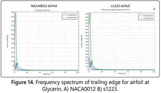
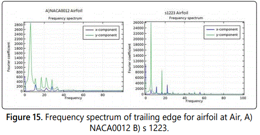
In addition, the fundamental frequencies are distinct with multiple harmonic peaks shown in figure 14 shows the main harmonic oscillation frequencies when using Glycerin as fluid, for both airfoils NACA0012 and s1223 the frequency for x displacement is 3 Hz and y displacement 2 Hz. In figure 15 also shows the main harmonic oscillation frequencies but using Air. The frequency for the x displacement is 12 Hz but in y displacement is around 8 Hz in NACA0012 airfoil. In s1223 airfoil the frequency in x displacement is 22 Hz and in y displacement is around 8Hz.
Conclusion
In the course of this research, 2D CFD/FSI was utilized to examine the cm-scale flapping mechanics with variations in size, weight and speed, (ii) the kinematics and dynamics to gain insight into lift and drag; flow characteristics surrounding a low Reynolds number wing and resulting criteria for selecting appropriate airfoil shapes, and flapping wing concepts for lift-to-drag ratio and aerodynamic performance. The fluid structure interaction (FSI) model is capable of predicting the behavior of the flow around flapping air foils, also considering that the mesh is sufficiently refined for achieving such results. Consequently, the FSI model is likely to face problems on the modeling of such flows. The flow around an elastic object results in self-induced oscillations of the structure. The results from our research show good agreement with Turek et al. [19] with the Glycerin fluid flow. The use of an extra fine Mesh concept is proven to be reliable for unsteady flows, as the comparison with other results cases from Turek et al. [19]. The research models have shown similarity on flow behavior and results. The mesh refining close to the flapping airfoil region is crucial for achieving an accurate modeling. In air fluid flow, the FSI simulations display two upstrokes and one down stroke for NACA0012 airfoil and two upstrokes and two down strokes for s1223 airfoil. Qualitatively, the FSI presents a flapping cycle that is close to the flapping wings behavior, showing that the FSI model can provide results of reasonable quality while saving computational effort.
The flapping flight of an airfoil fly shows two aerodynamic force peaks in each flapping stroke. The research shows that the first peak is due to rapid vorticity increase as the airfoil experiences fast pitching-up rotation, while the second peak is likely to be associated with wake-capturing. Overall, these two peaks account for a large portion of the total lift. While similar results are noted, our results are for a cm-scale application instead of an mm-scale application. The comparison in the results between both airfoils shows the s1223 airfoil is better than NACA0012 in laminar flow conditions. While our understanding of flapping wing dynamics and low Reynolds number flight involve largescale vortical motion flows, it is hypothesized that further research requires Navier Stokes and/or Turbulent models to understand further issues of hover, pitching, and landing.
References
- Menter FR. Two-Equation Eddy-Viscosity Models for Engineering Applications. AIAA Journal. 1994; 32(8): 1598-1605. doi: 10.2514/3.12149
- Theodorsen T. General Theory of Aerodynamic Instability and the mechanism of Flutter. NASA Technical Reports Server. 1949.
- Han JH, Lee JS, Kim DK. Bio-inspired flapping UAV Design: A University Perspective. In: Health Monitoring of Structural and Biological Systems. 2009; 7295: 72951I.
- Kessler S, Mark Spearing S, Kirkos G. Design of a High-g Unmanned Aerial Vehicle Structure. SAE Technical Paper. 2000.
- Hall KC, Pigott SA, Hall SR. Power Requirements for Large - Amplitude Flapping Flight. AIAA. 1997; 35(3): 352. doi: 10.2514/2.2324
- Hansen JR. The Bird is on the Wing: Aerodynamics and the Progress of the American Air-plane. Texas A& M University Press. 2004.
- Videler JJ. Aviation Flight. Oxford; Oxford University Press. 2006.
- Scholz MP. Advanced NXT: The Da Vinci Inventions Book. New York: A press. 2007.
- Nakata T, Liu H. Aerodynamic performance of a hovering hawkmoth with flexible wings: a computational approach. Proc Biol Sci. 2012; 279(1729): 722-731. doi: 10.1098/rspb.2011.1023
- Mountcastle AM, Daniel TL. Aerodynamic and functional consequences of wing compliance. Exp Fluids. 2009; 46: 873-882. doi: 10.1007/s00348-008-0607-0
- Barannyk O, Buckham BJ, Oshkai P. On performance of an oscillating plate underwater propulsion system with variable chordwise flexibility at different depths of submergence. J Fluids Struct. 2012; 28: 152-166. doi: 10.1016/j.jfluidstructs.2011.10.005
- Lienhard JH. The Engines of Our Ingenuity. NPR. KUHF-FM Houston. 2004.
- Old W. To Fly: The History of Wright Brothers. New York: Clarion Books; 2002.
- Calogero J, Frecker M, Wissa A, Hubbard JE. Optimization of a bend-twistand-sweep compliant mechanism. In: ASME 2014 Conference on Smart Materials, Adaptive Structures and Intelligent Systems. American Society of Mechanical Engineers. 2014.
- Zhang Z, Xie P, Ma O. Bio-inspired Trajectory Generation for UAV Perching Movement Based on Tau Theory. International Journal of Advanced Robotic Systems. 2014; 11(9): 141. doi: 10.5772/58898.
- Yashwanth T, Wissa A, Frecker M, Hubbard JE. Design and optimization of a contact-aided compliant mechanism for passive bending. Journal of Mechanisms and Robotics. 2014; 6(3). doi: 10.1115/1.4027702
- Wagner H. About the origin of the dynamic buoyancy of airfoils. Z Angew Math Mech. 1925; 5(1): 17-35.
- Von Karman TH, Sears WR. Airfoil Theory for Non-Uniform Motion. Journal of the Aeronautical Sciences. 1938; 5(10): 379-390. doi: 10.2514/8.674
- Turek S, Hron J. Proposal for Numerical Benchmarking of Fluid-Structure Interaction between an Elastic Object and Laminar Incompressible Flow. In: Bungartz HJ, Schfer M (eds). Fluid-Structure Interaction. Lecture Notes in Computational Science and Engineering, Volume 53. Springer, Berlin, Heidelberg. 2006.
- Pelletier A, Mueller TJ. Low Reynolds Number Aerodynamics of LowAspect-Ratio Thin/Flat/Cambered-Plate Wings. Journal of Aircraft. 2000; 37(5): 825-832. doi: 10.2514/2.2676
- Andro JY, Jacquin L. Frequency effects on the aerodynamic mechanisms of a heaving airfoil in a forward flight configuration. Aerosp Sci Technol. 2009; 13(1): 71-80. doi:10.1016/j.ast.2008.05.001
- Islam M, Amin MR, Shariff YM. Computational Analysis Of A High-Lift And Low Reynolds Number Airfoil At Turbulent Atmospheric Conditions. ASME 2009 International Mechanical Engineering Congress and Exposition. 2009; 9: 867-874. doi:10.1115/IMECE2009-10587
- Merabet A, Necib B. Characterisation of Wings with NACA 0012 Airfoils. Mechanical Engineering Department, Laboratory of Mechanics, Mentouri University Constantine 25000 Algeria. 2003.
- Bisplinghoff RL, Ashley H, Halfman RL. Aeroelasticity. NewYork: Dover; 1996.
- Thomas AL, Taylor GK, Srygley RB, Nudds RL, Bomphrey RJ. Dragonfly flight: free-flight and tethered flow visualizations reveal a diverse array of unsteady lift-generating mechanisms, controlled primarily via angle of attack. J Exp Biol. 2004; 207: 4299-4323. doi: 10.1242/jeb.01262
- Durand E. Time Domain Modeling of Unsteady Aerodynamic Forces on a Flapping Airfoil. Massachusetts Institute of Technology; 1998.
- Gerakopulos R, Yarusevych S. Novel Time-Resolved Pressure Measurements on an Airfoil at a Low Reynolds Number. AIAA Journal. 2012; 50(5): 1189-1200. doi: 10.2514/1.J051472
- Tucker VA, Parrott GC. Aerodynamics of gliding flight in a falcon and other birds. J Exp Biol. 1969; 52(2): 345-367.
- Eleni DC, Athanasios TI, Dionissios MP. Evaluation of the turbulence models for the simulation of the flow over a National Advisory Committee for Aeronautics (NACA) 0012 airfoil. Journal of Mechanical Engineering Research. 2012; 4(3): 100-111. doi: 10.5897/JMER11.074
- Parker K, Soria J, von Ellenrieder K. Characteristics of the Vortex Street Behind a Finite Aspect-Ratio Flapping Wing. 44th AIAA Aerospace Sciences Meeting and Exhibit. 2006: 1304. doi: 10.2514/6.2006-1304
- Turki S, Abbassi H, Nasrallah SB. Effect of the blockage ratio on the flow in a channel with a built-in square cylinder. Computational Mechanics. 2003; 33(1): 22-29.
- Gregory N, Reilly CLO. Low-Speed Aerodynamic Characteristics of NACA 0012 Aerofoil Sections, including the Effects of Upper-Surface Roughness Simulation Hoar Frost. NASA R& M 3726. 1970.

