Research Article
Modeling Thermal Part of Sulfur Recovery Unit and Simulation Based Analysis of Effects of Air Temperature on Entire Plant
1Turkish Petroleum Refineries Co. (TÜPRAŞ), R&D Centre, GuneyMah. Petrol Cad, 41790, Korfez, Kocaeli, Turkey
2Turkish Petroleum Refineries Co. (TÜPRAŞ), Izmit Refinery, GuneyMah. Petrol Cad, 41790, Korfez, Kocaeli, Turkey3Department of Chemical Engineering, Hacettepe University, Beytepe Campus Universiteler Mahallesi, 1596. Sok, 06800, Ankara, Turkey
*Corresponding author: Erdogan Alper, Department of Chemical Engineering, Hacettepe University, Beytepe Campus Universiteler Mahallesi, 1596. Sok, Ankara, Turkey, E-mail: ealper@hacettepe.edu.tr
Received: November 12, 2018 Accepted: November 29, 2018 Published: December 6, 2018
Citation: Dogru O, Guzel B, Gamze IS, et al. ModelingThermal Part of Sulfur Recovery Unit and Simulation Based Analysis of Effects of Air Temperature on Entire Plant. Int J Petrochem Res. 2018; 2(3): 223-229. doi: 10.18689/ijpr-1000139
Copyright: © 2018 The Author(s). This work is licensed under a Creative Commons Attribution 4.0 International License, which permits unrestricted use, distribution, and reproduction in any medium, provided the original work is properly cited.
Abstract
Sulfur in feedstocks are increasing steadily. Consequently, changes in regulations force industrial companies to operate Sulfur Recovery Units more efficiently. An industrial Sulfur Recovery Unit of TUPRAS, Turkey was modelled by Matlab by using simplified kinetics. Proposed model was validated with the industrial data of TUPRAS. The model represents the important species with minute deviation. According to the model proposed, conversion and recovery were found to be 65.24% and 86.88%, respectively; where they were calculated to be 64.91% and 82.72% in design case.
Moreover, effects of air temperature were studied in this work. According to the simulation results, up to $13,200/year can be saved by removing preheating. Because carbon content is essential in gas mixture, effects of COS and CS2 on catalytic part after this modification are found to be negligible in short term. This design change also increases the sulfur production by about 600 kg/day. On the other hand, amount of COS, CS2, H2S released from Selective Oxidation Reactor would be enhanced from 25 to 31 ppmmol, which increase overall SO2 emission from incinerator.
Keywords: Sulfur Recovery Unit, Modeling, Simulation
Introduction
Oil refineries and gas plants process enormous amounts of feedstock to obtain valuable products such as; fuel for vehicles, raw material for petrochemical industry. Recent regulations forced these sectors to lower the sulfur ingredient of both products and waste streams [1], significantly. On the other hand; beside their low cost, “opportunity crudes” with various compositions and increase in the sulfur content of the feed stocks [2] became pain in the neck when it comes to processing the crude oil. Moreover, because of the developing technology and constant demand [3], worldwide sulfur import and export values were halved in 4 years [4,5]. Above mentioned progresses faced companies to treat acid gas more effectively to reduce the emissions and operational costs.
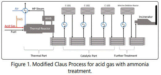
There are several methods; including catalytic, electrochemical processes [6]; to convert H2S into non-toxic derivations of sulfur. For industries with high capacity and high concentration, the most widely used technique is Claus Process, in which acid gas is passed through thermal and catalytic reactors to obtain elemental sulfur and steam. Figure 1 represents a Modified Claus Process Configuration [7-15].
Thermal part is the first medium that mixture of effluent compounds pass through and consists of a thermal reactor (TR) and a waste heat boiler (WHB). Thermal reactor breaks down most of the waste gas; including mainly H2S, NH3, water, and essentially mercaptans, paraffins, olefins, carbondioxide and other inert gases; at that point temperature may elevate up to 1500K and HP steam is obtained by means of WHB. Meanwhile, acid gas becomes extremely corrosive and leads cracks within the refractory. And the consequences may be catastrophic. On the other hand, temperature is one of the most critical parameters because it regulates the kinetics and is able to shift conversion towards both sides. Composition is another parameter that affect the products and hence, emissions. And finally, steam obtained from WHB is used in heat exchangers and electricity production. There by, it is economically beneficial to control and increase the energy efficiency. Summing these up, importance of modeling thermal part becomes undeniable [16-28].p After, acid gas proceeds towards catalytic part, in which substitution and hydrolysis processes are observed on Titania or Alumina catalysts unlike thermal part, in which oxidation processes take place without any catalyst. Catalytic part consists of two or three catalytic beds connected in series, generally. Some plants may have further treatment units in order to meet the demand of strict environmental regulations, which limit H2S conversion to minimum of 99% levels. These additional systems are told to enhance the sulfur recovery more than 99.9%. At the end, remaining gas is moved to incinerator to destroy S-containing molecules (e.g. COS, CS2, H2S) into SO2. SOx and NOx formed are released to atmosphere.
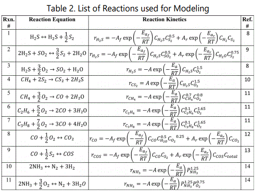
H2S conversion in these parts can be shown as:

During reaction (1), 1/3 of H2S is converted into SO2.

In reaction (2), 2/3 of H2S combines with SO2 produced to form elemental sulfur.
In the TR, pressure range isabout1.80 kg-f/cm2 and temperature varies between 1300-1500K in order to destroy undesired molecules but the refractory.
To maintain sufficient sulfur recovery, lower emissions and produce higher energy within certain limitations while considering safety and sustainability, the system should be operated carefully. A reliable model is necessary to reflect the characteristics of the processes. Modeling is also crucial for human and equipment safety, to study capacity status and to investigate environmental impacts.
Modeling Thermal Part
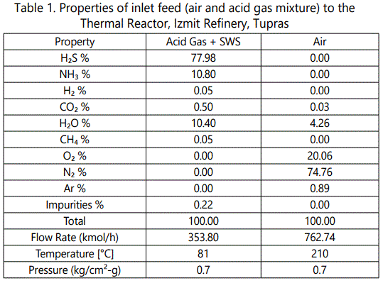
Elements of thermal part are thermal reactor, waste heat boiler and sulfur condenser. Inlet streams are acid gas (AG), gas from sour water stripper (SWS) and air. AG comes from Amine Gas Treatment Unit and is composed mainly of H2S (>90%). SWS gas contains 40% H2S, 40% NH3 and 20% H2O. AG and SWS is mixed before being fed to the furnace. Air can be enriched by oxygen supply. In this work, air is not enriched and carries 21% O2. table 1 shows the properties of inlet streams of one of SRUs in TUPRAS, Izmit Refinery.
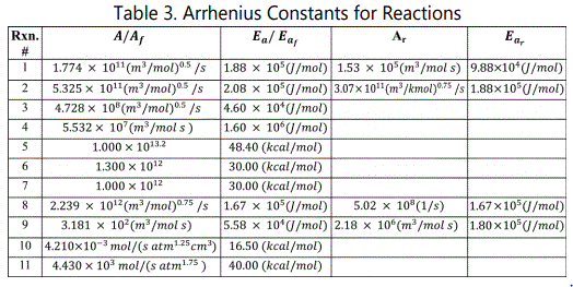
Reactor was modelled by using Fourth Order Runge-Kutta Method by assuming;
Mass balance for PFR for each component i(i=1:N) is:

Energy balance for PFR is:


For equation 6, 
Model results for the composition of important species and temperature profile within the reactor are shown in figure 2 and figure 3, respectively.
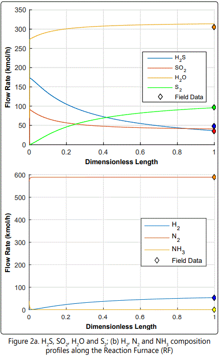
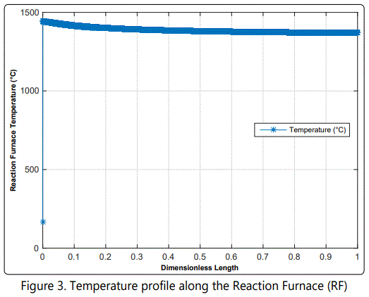
According to figure 2 (a), most of the H2S is oxidized then combined with SO2 to yield S2. As by product, H2O is formed. figure 2 (b) shows that all of the NH3 is reacted to N2 and H2. According to figure 3, Temperature rises immediately at the very beginning of the reactor, due to highly exothermic reactions. After a while, temperature declines smoothly due to endothermic reactions. This temperature decrease enhances combination (e.g. COS formation) reactions.
Validation
Simulation results of molar flow rates were compared with the design data of the Izmit Refinery, Tupras.
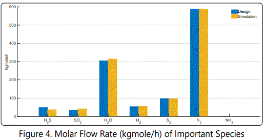
figure 4 represents important molecules that are present at the outlet of the reaction furnace in column chart. At the first glance, H2S and SO2 deviate from their design values. H2O, H2 and S2 are consistent with the design values with small deviations. Finally, it can be seen that all of the NH3 is converted to N2 as expected. All of the hydrocarbons are consumed and flow rates of COS and CS2 are found to be less than 0.2 kmol/h, which are negligible compared to above mentioned ones. Thereby, they were not shown in figures. The deviations are because of simplified reaction mechanisms and are negligible in practical perspective.
Effects of Inlet Air Temperature
Temperature is one of the most important parameters for Sulfur Recovery Process. It directly affects the kinetics and equilibrium. On the other hand, energy consumption and production can be altered with simple modifications. Air feed (Air0)is heated from 90°C upto 210°C and split into two streams; one (Air1) is for Reaction Furnace, other one(Air2)for Selective Oxidation Process, as shown in (Figure 5).
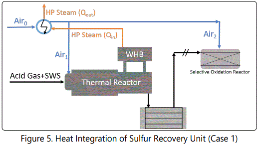
Unlike the other SRUs, this unit has heat integration: HP steam obtained from WHB is used to preheat the air. Effects of this heating process is investigated in next sections for entire plant
Reaction Furnace Temperature
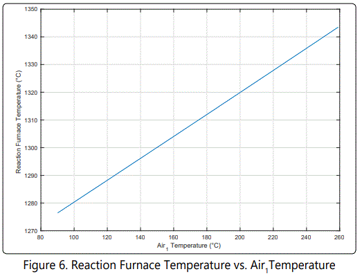
figure 6 shows that reaction furnace temperature increases as air temperature increases. That is because internal energy of the molecules approaches towards the activation energy.
Sulfur Production
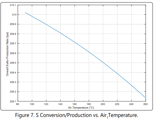
According to Figure 7, change in overall sulfur production is less than 1 ton between 90 and 260°C. Because the sulfur prices are about $50/t, varying temperature does not have a significant impact from financial perspective.
Catalysts
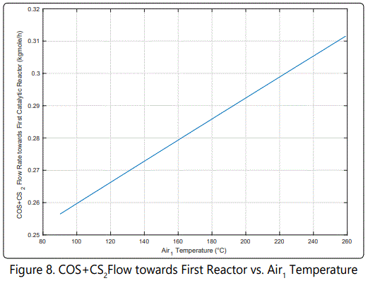
As can be seen from Figure 8 increasing air temperature augments COS and CS2 production, slightly. This increase may not affect the catalysts in short term.
Environmental Impacts
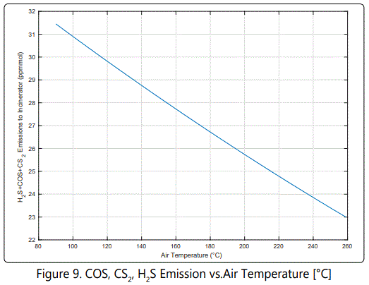
The regulations limits mainly SO2 emission. (Figure 9) shows that increasing air temperature from 120 to 260 °C decreases emissions 23%. This cumulative emission value is read on the stream before the incinerator. Because COS, CS2 and H2S molecules are oxidized to SO2, and they are considered as pollutants; they have to be controlled carefully.
Energy
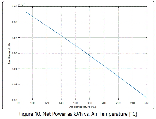
figure 5 shows that air is preheated by using HP steam obtained from WHB. Net power after the preheating process (Qin-Qout) is investigated in this section. The result is shown in (Figure 10).
Effect of Selective Oxidation Reactor (SOR) on Energy Consumption
According to previous section, it was shown that air consumes more energy than it actually generates via combustion reactions. That is due to air is completely warmed up but only partially used in furnace, rest is fed to Selective Oxidation Reactor. In this part, comparison between heating the air completely and partially is performed.
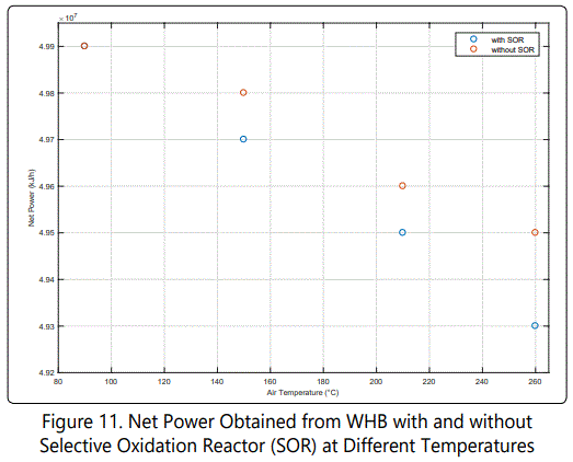
Figure 11 shows the impact of selective oxidation reactor. At the first glance, it can be seen that increasing air temperature enhances “Net Power Gap”. That is because a part of Air0 is heated unnecessarily. At 210°C, about 150,000 kJ/h power can be saved by de-attaching Air2 stream from the preheater. By assuming 90% of harvest efficiency, and using average HP steam value of the unit, $5200 can be saved per year if the SOR is de-attached from the preheater. (Figures 12 and 13) show two possible configurations to save energy. table 4 summarizes the results of these possibilities.
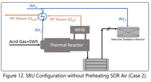
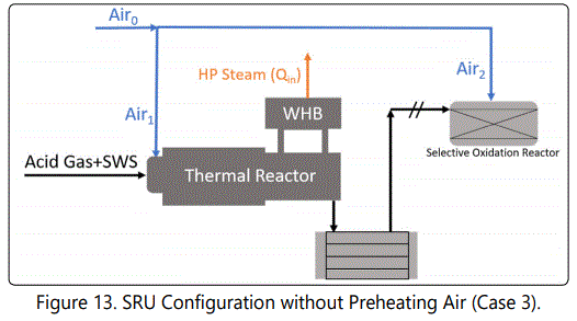
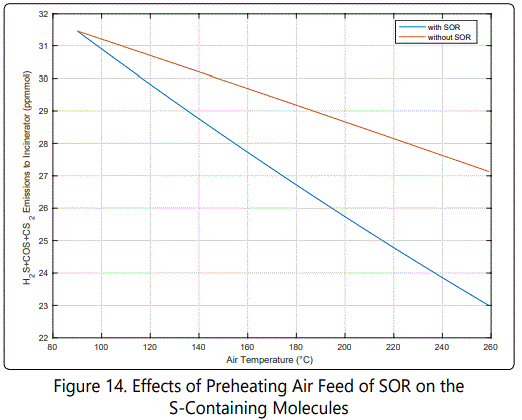
Figure 14 shows that increasing temperature decreases the emissions (that go towards the incinerator), which are oxidized into SO2. Changing configuration from design case into Case 2 (not preheating Air2) increases the emissions about 2 ppmmol at design temperature. Details are given in (Table 4).
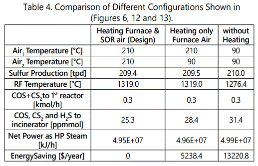
(Table 4) shows the results of possible configurations. It is possible to save $5.2k/year by de-attaching Air2 stream from the preheater and $13.2k/year by removing preheating system completely. On the other hand, these operations slightly increase S-containing molecules that are going to be oxidized to SO2 . Meanwhile, sulfur production do not change significantly. According to simulation results, without preheating (shown in Figure 13), RF temperature decreases as expected.
Conclusion
Sulfur content of the crude oils is increasing. Recent developments in the sulfur processing has decreased the sulfur prices. Regulations are becoming stricter for both sulfur contents in fuel and emissions during treatment processes. These circumstances force companies to operate refineries more efficiently.
In this work, a Sulfur Recovery Unit of TUPRAS refinery was modelled by using simplified kinetics. The model predicts the composition of important molecules with minor error values. Furthermore, a simulation performed in order to investigate the effects of air temperature for entire plant. Air temperature was found to have a positive relation with COS and CS2 flow rates towards the first catalytic reactor. However; due to low concentration, this incline can be neglected in short term. On the other hand, increasing air temperature decreases emissions, sulfur production and net power obtained by means of WHB.
A close research was performed upon the air preheating system and 2 configurations other than the design case was proposed. Regarding to these suggestions, sulfur production as well as concentration of the S-containing molecules may be enhanced slightly by decreasing the temperature of the feed air. By removing preheating system entirely, up to $13.2k/year can be saved whilst increasing emissions, slightly. For the sake of simplicity, reverse was not shown (i.e. preheating air much more), however emissions can be decreased by increasing the air temperature. In that case, RF temperature must be considered carefully.
Acknowledgement
This research was conducted in R&D Center of Turkish Petroleum Refineries Corporation (TUPRAS), Turkey.
References