

Research Article
Multi-stage membrane reactors for hydrogen production by ammonia decomposition
Department of Chemical Engineering, College of Engineering, King Saud University, P.O. Box 800, Riyadh 11421, Saudi Arabia
*Corresponding author: Mohamed EE Abashar, Department of Chemical Engineering, College of Engineering, King Saud University, P.O. Box 800, Riyadh 11421, Saudi Arabia, E-mail: mabashar@KSU.EDU.SA
Received: November 15, 2017 Accepted: January 28, 2018 Published: February 3, 2018
Citation: Abashar MEE. Multi-stage membrane reactors for hydrogen production by ammonia decomposition. Int J Petrochem Res. 2018; 2(1): 109-115. doi: 10.18689/ijpr-1000120
Copyright: © 2018 The Author(s). This work is licensed under a Creative Commons Attribution 4.0 International License, which permits unrestricted use, distribution, and reproduction in any medium, provided the original work is properly cited.
Abstract
A heterogeneous mathematical model is used to simulate a cascade of multi-stage fixed bed membrane reactors (MSFBMR) for the decomposition of ammonia. The numerical results show that a single fixed bed membrane reactor (FBMR) exhibits a poor performance and limited by the kinetics to give 29.49% exit ammonia conversion, whereas efficient seven multi-stage beds achieve 100% ammonia conversion. An effective hydrogen permeation zone has been identified by a critical point. It is observed that the locus of the total inter-stage heating load assumes a maximum inflection point. The results show that the multi-stage fixed bed membrane reactors configuration has many benefits and can the future generation of reactors for production of hydrogen.
Keywords: Ammonia decomposition, hydrogen, membrane reactor, modeling, multistage reactors.
Introduction
In recent years the demand for ultra-clean hydrogen is increased significantly to power polymer electrolyte membrane (PEM) fuel cells. [1, 2]. Conventional steam reformers produce hydrogen with a high level of traces of impurities not suitable for the PEM. Today, hydrogen perm-selective composite membranes produce high quality of hydrogen. Moreover, they play an important role in displacement of thermodynamic equilibriums [3-6] and enhancement of the reactors performance. Further improvements are still needed for best design and operation.
Decomposition of ammonia is an attractive process for pure hydrogen production. The reaction gives only hydrogen and nitrogen. The reaction has received much attention for on-site (local) hydrogen production. Several theoretical studies have been published on ammonia decomposition. However, these studies have been largely directed toward the removal of ammonia traces as a pollutant [6-8]. The chemical engineering literature contains limited theoretical and modeling studies for hydrogen production by ammonia decomposition at the level of experimental bench scale reactors [9]. In fact, more modeling and simulation studies for different reactors configurations for ammonia decomposition are needed.
Surprisingly, theoretical studies of multi-stage fixed bed membrane reactors (MSFBMR) for the decomposition of ammonia are scarce. In this study, the mathematical modeling and numerical simulation approach has been implemented to investigate application potential of multi-stage membrane reactors for production of ultra-clean hydrogen. The benefits that can be gained by these reactors configurations are explored. Moreover, deeper insight understanding of the process might be gained. Furthermore, the effect of the key parameters on the performance of the MSFBMR are considered.
Rate of reaction
The decomposition of ammonia is represented by the following reaction:
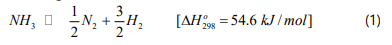
The rate of reaction rate is given by the Temkin [10-12]:
Where fi is the fugacity of component i. The equilibrium reaction constant is by the following equation:

Where T is the absolute temperature (K).
The mathematical modeling of the FBMR
A rigorous two-dimensional heterogeneous model is
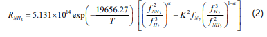
formulated for ammonia decomposition. A schematic diagram
for two multi-stage fixed bed membrane reactors is presented
in Figure 1. The following assumptions are used to develop
the mathematical model:
1. Steady state conditions.
2. The reactor operates under isothermal conditions.
3. The membrane has exclusive selectivity for hydrogen.
4. An isothermal catalyst pellet.
5. Negligible axial dispersion.
6. Cylindrical symmetry.
7. Spherical catalyst pellet with symmetric geometry.
8. Negligible external mass resistance for the catalyst pellet.
Tube side
The material balance equation for component i on the tube side is given as:

Where Ci is the concentration of component i, Ao is x-sectional area of the bed, ul is the axial velocity, e1 is porosity of the bed, Dei effective diffusivity coefficient of component i, gi is the generalized stiochiometric coefficient of component i (negative for reactants) and h is the effectiveness factor.
The effective diffusivity coefficient is calculated using:
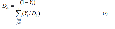
Fuller, Schettler and Giddings correlation is used for the binary diffusivity (Dij) :
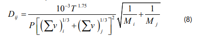
Where T is temperature, P is pressure, v is the atomic diffusion volume and M is the molecular weight.
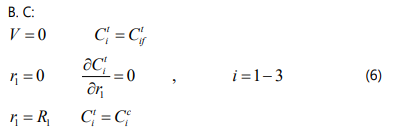
Ceramic support
The component mass balance equations for the ceramic support is given by:
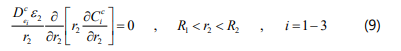
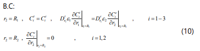
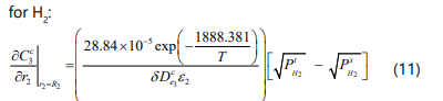
Where e2 is porosity of the ceramic support and d is the membrane thickness.
The conversion of ammonia is given by:
The global orthogonal collocation technique [13] is used to change the partial differential equations into ODEs which can be integrated directly.
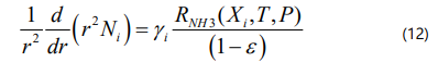
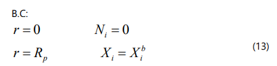
Catalyst pellet
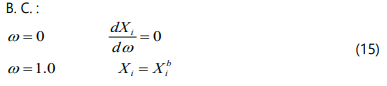
The material balance for component i in the catalyst pellet is given by:
The component material balance equations in a dimensionless form can be written as :
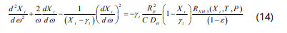
where ω is the dimensionless coordinate and C is the total concentration. The effective diffusion coefficient is given by :
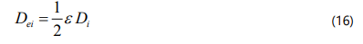
Where e is the intraparticle porosity and Di is bulk diffusion coefficient of component i:
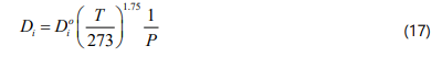
The diffusion coefficient of component i (Di°) at 0°C and 1 atm is given by:
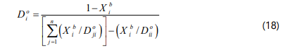
and Xi is given by:
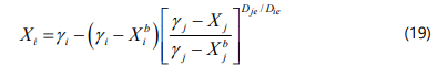
The effectiveness factor:
Where X is the mole fraction vector.
Permeation side
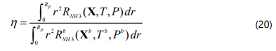
On the permeation side the material balance for hydrogen is given by [14]:
Results and Discussion
Figure 2 compares the performance of three adiabatic reactors configuration for ammonia decomposition. The fixed bed membrane reactor (FBMR) at 40.0 bar, multi-stage fixed bed reactor (MSFBR) with inter-stage heating at 1.0 bar and multistage fixed bed membrane reactor (MSFBMR) with inter-stage heating at 40.0 bar. A feed temperature of 600°C is used for all configurations and a maximum feed temperature (Tmax) is considered to be 900°C [15, 16]. In the multi-stage configurations each bed has a volume of 0.1 m3 . As it can be seen, the performance of the FBMR is strongly affected by the severe drop of the temperature and limited by the kinetics due to the low temperature and the result of that a low exit ammonia conversion of 29.49% is attained. The MSFBMR configuration achieves 100% ammonia conversion by six beds and a small final bed (Bed7 ) of a volume of 0.011 m3 . It is obvious that this configuration works remarkably well beyond the thermodynamic equilibrium at 40 bar due to the imposed membrane. For fair comparison, the same number of beds is used for the MSFBR configuration. The exit final ammonia conversion achieved by this configuration is 92.37%. It can be seen also, that MSFBMR configuration is superior to the MSFBR configuration with respect to ammonia conversion in all beds. These results demonstrate the excellent and promising performance of the MSFBMR configuration.
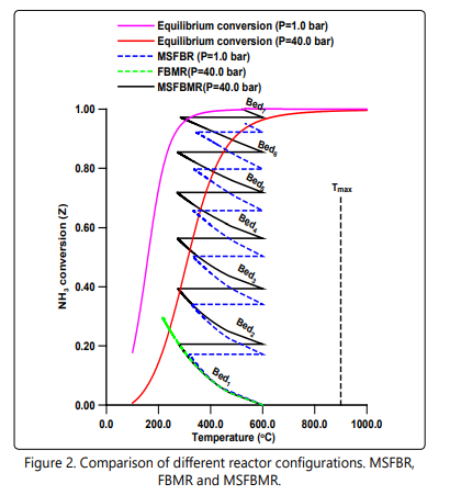
Figure 3 shows the effect of the pressure on the exit ammonia conversion for the MSFBMR configuration. At a low pressure each bed of the MSFBMR configuration works similar to a fixed bed reactor due to virtually weak hydrogen permeation. It is clearly shown that, the exit ammonia conversion decreases with the increase of the pressure due to its negative influence on the thermodynamic equilibrium to a critical inflection point beyond which the role of the membrane comes to dominate and developing an effective permeation zone. Note that this critical point needs to be identified to determine the critical minimum operating pressure for the MSFBMR configuration.
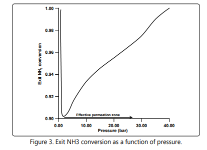
Figure 4a shows the hydrogen molar flow rate in the reaction and permeation sides for the MSFBMR configuration. As it can be shown that the hydrogen permeation is high in the first bed and decreases progressively to the last bed, this could be due to the availability of the hydrogen in the reaction side. The cumulative hydrogen flow rate in the permeation side is presented in Figure 4b. The result is consistent with the results shown in Figure 4a and implies progressive increase in the cumulative hydrogen flow rate.
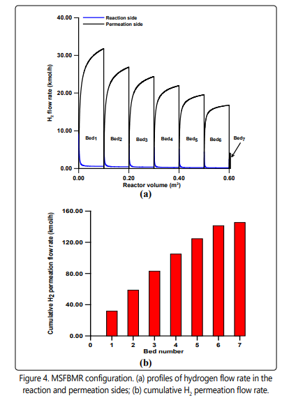
Figure 5a shows inter-stage heat load per heat exchanger (Qj ) and cumulative inter-stage heat load (ΣQ). It is shown clearly that the inter-stage heat load seems to decrease linearly with the increase of the number of heat exchangers due to the decrease of the mixture mass flow rate and the enthalpy as a result of hydrogen permeation as shown in Figure 5b.
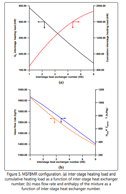
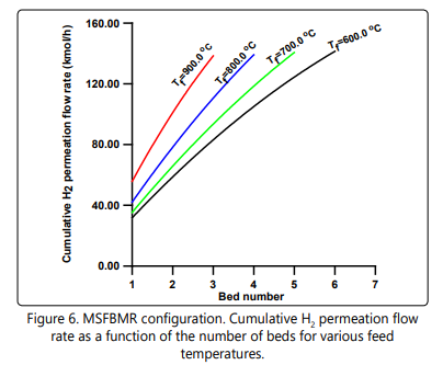
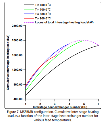
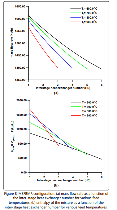
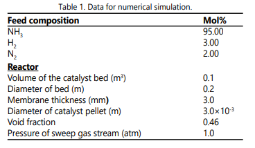
Figure 6 shows the cumulative hydrogen permeation flow rate as a function of the number of beds for various feed temperatures. Note that all the feed temperatures give almost the same final total quantity of permeating hydrogen independent of the number of beds used. The corresponding cumulative interstage heating load is depicted in Figure 7. It is interesting to note that the total inter-stage heating load at the Tf = 900°C is the least compared to other feed temperatures in spite of the fact that it has the highest temperature drop per heat exchanger as clearly shown in Figure 2 (Tf = 600°C ). Also, in Figure 7 one can see that the locus of the total inter-stage heating load assumes an inflection point of maximum nature. This phenomenon might be due to the complex interaction of the hydrogen permeation, heat capacity, temperature drop and the number of beds. Figures. 8 a and b might help us to have some understanding of this phenomenon. Figure 8a shows that the mass flow rate decreases along the heat exchangers due to separation of hydrogen. Also, the mass flow rate decreases as the feed temperature increases from 600°C to 900°C. This is could be due to the fact that a high feed temperature has a profound positive effect on the ammonia decomposition kinetics and its thermodynamic equilibrium. At the first heat exchanger the enthalpy of the mixture increases as the feed temperature increases from 600°C to 900°C as shown in Figure 8 b. The result of an overall effect is that the heat load increases as the feed temperature increases as shown in Figure 7. However, this sequence of events does not remain after the first heat exchanger. As the number of heat exchangers increases after the first heat exchanger, the final exit enthalpy of the mixture decreases as the feed temperature decreases opposing the trend of the mass flow rate as shown in Figures 8 a and b. This is the main reason for the formation of the maximum shown in Figure 7. The data for numerical simulation are listed in Table 1.
Conclusions
Ammonia decomposition is an attractive carbon free single step process for production of hydrogen. In this paper, the conducted numerical simulation has shown that the multi-stage membrane reactors (MSFBMR) for ammonia decomposition have significant advantages over the single fixed bed membrane reactor (FBMR). Also, the MSFBMRs have attractive potential application for efficient production of ultraclean hydrogen suitable for the PEM fuel cells. The results suggested that the multi-sage configuration is suitable for the on-site hydrogen production. The hydrogen membrane, number of beds and the inter-stage heat exchangers strongly influenced the performance of the MSFBMR. Since, the diffusion limitations effect is shown to be confined to very small regions in each bed a pseudo-homogeneous model can be utilized as an initial trial model to extract some features of the process. The results of this preliminary study might have fundamental importance in designing of the MSFBMR for the ammonia decomposition. Optimization of this process will be addressed in the future research. To this end, the compelling merits of the MSFBMR dedicate that intensive efforts still needed in academia and industry levels.
Nomenclature
| C | total concentration, kmol/m3 |
| Cpi | specific heat of component i, kJ/kmol K |
| Cpjmix | specific heat of the mixture at heat exchange j, kJ/kg °C |
| dH2 | diameter of hydrogen membrane tube (m) |
| Di | bulk diffusion coefficient of component i, m2 /h |
| Dio | diffusion coefficient of component i at 0 °C and 1 atm, m2 /h |
| Djio | diffusion coefficient of component j in component i,m2 /h |
| Die | effective diffusion coefficient of component i, m2 /h |
| fi | fugacity of component i |
| Fi | molar flow rate of component i, kmol/h |
| Fio | initial molar flow rate of component i, kmol/h |
| ?H | enthalpy change of reaction, kJ/kmol |
| JH2 | hydrogen permeation rate, kmol/h m3 |
| K | equilibrium constant, kPa-1 |
| mjmix | mass flow rate of the mixture at heat exchange j, kg/h |
| Ni | molar flux of component i in r direction |
| Nbed | number of beds |
| P | total pressure, kPa |
| Pi | partial pressure of component i, kPa |
| Qj | heat load of heat exchanger j, kW |
| r | radial coordinate of spherical catalyst pellet, m |
| R | gas constant, kJ/mol K |
| Rp | radius of spherical pellet, m |
| RNH3 | reaction rate of ammonia decomposition, kmol/h m3 |
| T | temperature, K |
| Tj | inlet temperature of heat exchanger j, °C |
| Tf | feed temperature, °C |
| V | reactor volume, m3 |
| Xi | mole fraction of component i inside catalyst pellet |
| Yi | mole fraction of component i |
| Z | ammonia conversion |
| Greek letters | |
| α | kinetic parameter |
| γi | generalized stoichiometric coefficient of component i |
| δ | thickness of hydrogen membrane, mm |
| ε | packed bed void fraction |
| η | effectiveness factor |
| λ | intraparticle porosity |
| φi | fugacity coefficient of component i |
| ω | dimensionless radial coordinate of spherical catalyst pellet |
| Superscript | |
| b | bulk |
| p | permeation side |
| r | reaction side |
References
- Zamel N, Lix X. Effective transport properties for polymer electrolyte membrane fuel cells-With a focus on the gas diffusion layer. Prog. Energy and Combustion Sci. 2013; 39(1): 111-46. doi: 10.1016/j.pecs.2012.07.002
- Uribe FA, Gottesfeld S, Zawodzinski TA. Effect of ammonia as potential fuel impurity on proton exchange membrane fuel cell performance. J. Electrochem. Soc. 2002; 149(3): A293-96. doi: 10.1149/1.1447221
- Hughes R. HComposite palladium membranes for catalytic membrane reactors. Membr Tech. 2001; 131: 9-13. doi: 10.1016/S0958-2118(01)80152-X
- Abashar MEE. Integrated catalytic membrane reactors for decomposition of ammonia. Chem Eng Process. 2002; 41(5): 403-12. doi: 10.1016/S0255- 2701(01)00169-6
- Abashar MEE, Al-Sughair YS, Al-Mutaz IS. Investigation of low temperature decomposition of ammonia using spatially patterned catalytic membrane reactors. Appl Catal A. 2002; 236(1-2): 35-53. doi: 10.1016/S0926- 860X(02)00272-7
- Garcia-Garcia FR, Hua-Ma Y, Rodriguez-Ramos I, Guerrero-Ruiz A. High purity hydrogen production by low temperature catalytic ammonia decomposition in a multifunctional membrane reactor. Catal Commun. 2008; 9(3): 482-6. doi: 10.1016/j.catcom.2007.07.036
- Di Carlo A, DellʼEra A, Del Prete Z. 3D simulation of hydrogen production by ammonia decomposition in a catalytic membrane reactor. Int J Hydrogen Energy. 2011; 36(18): 11815-24. doi: 10.1016/j. ijhydene.2011.06.029
- Gobina EN, Oklany JS, Hughes R. Elimination of ammonia from coal gasification streams by using a catalytic membrane reactor. Ind Eng Chem Res. 1995; 34(11): 3777-83. doi: 10.1021/ie00038a014
- Chein RY, Chen YC, Chang CS, Chung JN. Numerical modelling of hydrogen production from ammonia decomposition for fuel cell applications. Int J Hydrogen Energy. 2010; 35(2): 589-97. doi: 10.1016/j. ijhydene.2009.10.098
- Temkin M, Pyzhev V. Kinetics of the synthesis of ammonia on promoted iron catalysts. Acta Physicochim URRS. 1940; 12: 327.
- Singh CPP, Saraf DN. Simulation of ammonia synthesis reactors. Ind Eng Chem Process Des Dev. 1979; 18: 364-70. doi: 10.1021/i260071a002
- Dyson DC, Simon JM. A Kinetic expression with diffusion correction for ammonia synthesis on industrial catalyst. Ind Eng Chem Fundam. 1968; 7(4): 605-10. doi: 10.1021/i160028a013
- Villadsen JV, Michelsen ML.Sorensen RZ, Klerke A, Quaade U, Jensen S, Hansen O, et al. Promoted Ru on high surface area graphite for efficient miniaturised production of hydrogen from ammonia. Catal Lett. 2006; 112(1-2): 77-81. doi: 10.1007/ s10562-006-0167-yDi Carlo A, DellʼEra A, Del Prete Z. Ammonia decomposition over commercial Ru/Al2 O3 catalyst: An experimental evaluation at different operative pressures and temperatures. Int J Hydrogen Energy. 2014; 39(2): 808-14. doi: 10.1016/j.ijhydene.2013.10.110Chiuta S, Everson RC, Neomagus HWJP, Gryp P, Bessarabov DG. Reactor technology options for distributed hydrogen generation via ammonia decomposition: A review. Int J Hydrogen Energy. 2013; 38(35): 14968-91. doi: 10.1016/j.ijhydene.2013.09.067
