Review Article
A Comprehensive Review on the Advancement of Non-damaging Drilling Fluids
Petroleum Engineering Department, Khalifa University of Science and Technology, Petroleum Institute, P.O. Box 2533, Abu Dhabi, United Arab Emirates
*Corresponding author: Bisweswar Ghosh, Associate Professor, The Petroleum Institute, P.O. Box 2533, Abu Dhabi, United Arab Emirates, E-mail: bghosh@pi.ac.ae
Received: March 5, 2017 Accepted: April 17, 2017 Published: May 2, 2017
Citation: Alcheikh IM, Ghosh B. A Comprehensive Review on the Advancement of Non-damaging Drilling Fluids. Int J Petrochem Res. 2017; 1(1): 61-72. doi: 10.18689/ijpr-1000111
Copyright: © 2017 The Author(s). This work is licensed under a Creative Commons Attribution 4.0 International License, which permits unrestricted use, distribution, and reproduction in any medium, provided the original work is properly cited.
Abstract
The ever-increasing targets of drilling depth and reach, coupled with locational
disadvantages have driven the oilfield drilling operations into new technology frontiers. Drilling fluids being an essential component of any successful drilling operation, adequate understanding of the impact of drilling fluid characteristics can eliminate a
range of difficulties encountered during drilling operations and reduce drilling cost
significantly.
This article presents a comprehensive review of various types of drilling fluid systems
and technology advancements and also the significant challenges faced by a drilling
fluid engineer, starting with the basics and ending with extreme reservoir Conditions, with special emphasis on non-damaging drilling fluids. This paper is specially written for
fresh petroleum engineering graduates and entry level drilling fluid engineers and
drilling engineers as well as for drilling fluid research groups who would find many
important information for a given drilling and reservoir challenge.
Key Words: Drilling fluid, Water base mud, Oil base mud, Mud formation damage
Introduction
Drilling fluids and Drilling muds are sometimes used interchangeably; however, the
term "fluids" is much wider and is preferred by most drilling companies and authors. Several definitions are used by the industry to describe the drilling fluids without placing
any restrictions either on the composition or on the properties of the drilling fluids. Some of the available definitions, taken from different sources are mentioned below: A drilling fluid is defined as the fluid that encompasses all of the compositions used
to aid the production and removal of cuttings from a borehole in the earth [1].
Baker Hughes Drilling Fluids Reference Manual, mentions that a drilling fluid is a
fluid formulated with chemicals to obtain specific chemical and physical characteristics
for circulating during the rotary drilling process [2].
The American Petroleum Institute (API) defines the drilling fluid as a circulating fluid
used in rotary drilling to perform any or all of the various functions required in drilling
operations [3].
According to Schlumberger Oilfield Glossary, a drilling fluid is defined as any number
of liquid and gaseous fluids and mixtures of fluids and solids used in operations to drill
boreholes into the earth [4].
It is worth noting that the wide and restriction free definition adopted by the
industry has given the opportunity to new compositions and properties of drilling fluids
to arise throughout the history of drilling, which is the topic of discussion in this article
Functions and Properties of Drilling Fluids
During the primitive stages of oil well drilling, drilling
fluids were initially required to function as a vehicle for the
removal of drill cuttings from the borehole while and after
drilling. As drilling operations continued towards deeper
reservoirs and more challenging environment (such as deep
water and higher temperature formations), new conditions
were encountered and new and more demanding functions
were required from the drilling fluids. Below are some of the
minimum required functions of drilling fluids [5]:
• Removing cuttings from the hole
• Cleaning the hole bottom
• Cooling and lubricating the bit and drill pipe
• Preventing cuttings settling in the hole and surface
pits
• Deposition of impermeable wall cake to prevent fluid
loss.
• Overcoming formation pressures to prevent ingress
of oil, gas or water.
With passage of time and enhanced awareness on health
safety and environment and also concerns on economics, new
criteria are introduced, in addition to the normal drilling fluid
functions. Below are some of these additional requirements
that the drilling fluids are expected to possess [1]:
• Not to injure drilling personnel
• Not to be damaging or offensive to the environment, • Should not require unusual or expensive methods of
completion of the drilled hole
• Should not interfere with the normal productivity of
the fluid-bearing formation
• Not to corrode or cause excessive wear of drilling
equipment.
In order for drilling fluids to perform their required
functions effectively, several principal properties related to
their performance should be controlled and evaluated. The
principle properties of drilling fluids to be controlled within a
given limit are:
• Specific weight
• Particle size and shape
• Colloidal properties
• Flow properties
• Filtration properties
• pH
• Alkalinity
• Cation exchange capacity
• Electrical conductivity
• Lubricity
• Corrosivity
Evaluation and testing of the drilling fluid properties are
described in the API publication RP 13B-2 which includes
equipment and detailed laboratory procedures [6].
Classification of Drilling Fluids
Drilling fluids have undergone significant development in
various aspects keeping pace with the advancement of drilling technology, since the time they were first used in the rotary
drilling process sometime between 1887 and 1901 [7]. Such
development resulted in an obvious increase in number of
available drilling fluid types and thus a continuous update of
drilling fluids classification criteria was necessary. Several
classification attempts taken from different sources are given
below:
Drilling fluids can be classified on the basis of their
principal component into water, oil and gas base drilling fluids
[1]. This classification was the most commonly used [7].
All drilling fluids may be divided into two main categories
based on their specific weight [7]. Drilling fluids with specific
weight equal or less to 78 lb.\cu ft. may be considered as nonweighted, whereas any drilling fluid that is heavier than 83 lb.\
cu ft. may be considered as weighted drilling fluids.
Drilling fluids can also be classified based on several
aspects like their fluid phase, alkalinity, dispersion, the type of
chemicals used in their formulation and the degrees of
inhibition. According to such classification, drilling fluids are
divided into five main categories [8].
• Freshwater muds-dispersed systems
• Inhibited muds-dispersed systems
• Low solids muds-nondispersed systems
• Non-aqueous fluids
• Oil-base muds
• Invert emulsion muds
According to ASME Shale Shaker Committee [9], drilling
fluids are classified (according to the type of the base fluid
and other primary ingredients), into gaseous, aqueous and
non-aqueous drilling fluids. Detailed and farther classifications
can be employed to describe the composition of the fluids
more precisely.
Due to different bodies and opinions from experts in the
classification of drilling fluids, often more confusion were
created, thus by singling out the main component (the fluid
media) that clearly defines both the function and performance, drilling fluids are classified into water-base, oil-base and
gaseous drilling fluids and adopted by the industry [4].
Liquid Drilling Fluids
Liquid Drilling fluids are classified into water-base muds
and oil-base muds with water and oil being the continuous
phase respectively. Water-base muds may contain oil and oilbase
muds may contain water in their formulation [10].The
amount of water present in oil-base muds should not exceed
the amount of oil and vice versa [3]. The most commonly used
drilling fluids are the water-base muds, whereas oil-base
muds are limited to drilling sensitive formations with special
drilling requirements (to be discussed later) or formations that
are affected adversely by water-base muds. Water-base muds
are less expensive and require less stringent pollution control
procedures compared to the oil-base muds [11].Further
description of water-base muds and oil-base muds will be
covered in the following sections.
Water-base muds (WBM)
WBMs are classified into different categories based on
their compositions or functions, as well as whether they are
used for pay-zone drilling or non-pay-zone drilling. Conventional compositions can be used for preparing WBM
for non-pay zone drilling with less worries about formation
damage, taking advantage of its low cost. However, for a
drilling fluid to be used for pay zone drilling, the most
important property should be minimum damaging effect or if
possible non-damaging to the pay formation. For a waterbase
mud to be a non-damaging fluid, several modifications
within the composition and properties must be made. The
resultant drilling fluid is called the drill-in fluid and is described
further below.
Water-base mud types include;
• Spud muds
• Dispersed muds
• Lime muds
• Gypsum muds
• Salt water muds
• Non-dispersed polymer muds
• Inhibitive potassium muds
• Cationic muds
• Mixed metal hydroxide muds.
The widespread use of water-based muds is attributed to
its universal distribution of water, its low cost, compatibility
with human health and the satisfactory nature in its application. Moreover, mud cuttings resulting from drilling using waterbase
muds can be easily disposed onsite at most onshore and
offshore locations. This in turn reduces the total drilling costs
as no extensive and expensive treatment or transportation is
required prior to cuttings disposal.
Despite the environmental compatibility, water-base
muds with conventional compositions possess several
deficiencies related to their performance. Poor performance
against shale inhibition, lubricity and thermal stability are
examples of such deficiencies [3]. Therefore, the composition
of water-base muds is modified through the use of special
additives in order to enhance their performance against the
previously mentioned deficiencies.
The usual composition of water-base muds contain clays, water soluble chemicals (including salts), a pH control additive (hydroxyl source), and one or more organic polymers, surfactants, and deflocculants [2]. Other special dissolved
substances may include rheology controller, friction reducers
and thermal stabilizer [3]. Newly introduced chemicals to
encounter extreme temperature and pressure (Perfluoro-
Polyethers) base polymers and surfactants, multiwall carbon
nanotubes based WBM, are also under development and trial
[12] [13]. Insoluble and suspended materials such as polymers, barite, clays, and cuttings in suspension may be contained
within water-base muds.
Poor thermal stability of conventional water-base muds
refer to their viscosity decrease with increasing temperature. A decrease in viscosity results in several problems such as a
reduction of the cutting lifting ability of the water-base muds. The poor thermal stability can be treated by adding formate based salts such as potassium and sodium formats in the
polymer-based aqueous fluids [14] [15] [16]. Other less
expensive means are also available. Xanthan gum and
polyacrylamide are added to water-base fluids to enhance
thermal stability up to a certain temperature limit based on
the polymer type and their molecular structure. Thermal
degradation and special chemical application is discussed in a
later section of this article.
Shale encapsulators are added to water-base muds to
reduce the swelling tendency of the shale formations in the
presence of water. Quaternary polyacrylamide is the
conventional shale encapsulator used in most cases. Other
commercial shale encapsulators for low salinity conditions
and fresh water muds are available [17]. Specific formulations
that provide membrane formation over a specific shale
formation are used to increase the wellbore stability by
allowing the relatively free water movement through the
shale and significantly restricting the movement of ions into
the shale.
Modification of the water-base composition to account
for its deficiencies resulted in an increase in its cost, however
its environmental compatibility compared to other drilling
fluids has kept it as the most widely used and accepted drilling
fluid.
Oil-base muds (OBM)
The continuous phase of OBM is a liquid hydrocarbon
instead of water. Conventional OBM contains diesel as the
continuous phase due to its favorable viscosity characteristics, low flammability and low solvency for rubber elements in
drilling equipment [11].Light crude oil is also used extensively
as the base fluid, however due to the relatively large amounts
of aromatics and n-olefins present in crude oils, they generally
exceeds the toxicity limit which encouraged the use of low
toxicity mineral oils and ester base synthetic oils [18] [19]. Water can be present in oil-base muds intentionally (for
economic reasons) or unintentionally during drilling
operations. The presence of water in oil-base muds will form
an emulsion. If the water is added intentionally to the oil-base
muds, the resulting mixture is called an invert emulsion mud. The amount of water in an invert emulsion is generally more
than 5% of the entire composition [3]. On both conditions, water-emulsifying agents must be added, to prevent the
coalescence and settlement of water droplets out of the
emulsion [20]. A wettability reversal agent is also added to
invert the tendency of solids being water wet to being oil wet. This in turn prevents the solids from being absorbed by the
water which can lead to high viscosities and eventual
settlement of barite. Other materials like clays or colloidal
asphalts to provide viscosity, weighting agents and other
additives are also added to the oil-base muds.
As mentioned previously, oil-base muds are used for
special purpose drilling, having advantage of their unmatched
performance. The special advantages of OBM are their good
rheological properties at temperatures as high as 500oF, more
inhibitive than inhibitive water base muds, effective against all
types of corrosion, superior lubricating characteristics, and permits mud densities as low as 7.5 ppg. Additional advantages
include resistance to chemical contamination, gauge hole in
evaporate formations, reduced production damage, and
ability to be re-used [2].
OBM vs WBM
It is obvious that there are several advantages of using
water base muds over the oil base muds. Examples of such
advantages are being less damaging to the formation media
compared to oil based muds (in terms of wettability alteration) and the possibility of cuttings to be disposed on site unlike
the coated cuttings resulting from oil-base muds. Water base
muds have undergone several important developments
allowing them to be used as an alternative to oil base muds in
some cases [21]. However, with complex types of wells such as
deviated and S-shape wells, using the water base muds
becomes more challenging because of higher friction and
stuck pipe issues. The most important reason is due to the fact
that water base muds are not naturally lubricious unlike the
oil base muds. Though lubrication additives can be added to
water base muds, it is much convenient to use oil base muds
in such cases as they are readily lubricous. In addition to being
lubricious, oil base muds provide a higher rate of penetration
as well as more stable wellbore as they have been proven to
have very low tendency of soaking the formation. The other
advantage of OBM over WBM can be summarized as follows:
1. Water-based mud can swell shale formation, collapse
boreholes and impact drilling outcome in the shale
formation drilling.
2. Gases produced among shale cracks whose nonorganic
part is possibly aqueous wetting phase can
be easily displaced by water, offsetting the well
loggings.
3. Water-based mud can easily block the layers of very
low permeability and influence the capability to
produce hydrocarbon.
4. Oil-based mud can support the shale formation and
its oil molecules cannot penetrate into tiny organic
and non-organic pores under the capillary pressure.
5. Oil-based mud typically creates thin mud cake. This
reduces the risk for stuck-pipe problem.
6. Oil-based mud can be treated and reused; thereby in
the long run overall drilling mud cost is reduced.
7. Oil base as external phase is good lubricant so it
greatly reduces drilling torque.
8. Hydrate formation problem at high pressure wells
such as deep water drilling can be avoided by using
oil base mud.
9. Typically, when drilling with oil base mud, gauge hole
can be easily achieved.
In spite of the above advantages there are several
disadvantages of using OBM, particularly in the offshore
environment [22].
1. Environmental concern- OBM and the cutting
generated during drilling with OBM are considered as
toxic waste therefore it cannot be disposed directly into the environment unless treated well to meet the
local regulations. Needs a good waste management
while drilling with oil base mud.
2. Personnel Heath – OBM has hazardous vapors which
will cause health problem to the working personnel. Need to use proper protective equipment in order to
handle it. OBM vapor can irritate worker's skin. 3. Cost – Cost of OBM is much higher than most WBMs
in terms of cost per barrel.
4. Gas kick detection – Gas kick is very difficult to identify
while drilling with OBM because gas is soluble in oil. The gas kick can only be detected through volume
gain in the mud pit. This enhances the drilling hazard.
5. Cleanliness –More time and effort is required to clean
drilling area where the OBM spills.
6. Equipment damage– Rubber parts are easily
deteriorated by oil base mud. Therefore, frequently
check of rubber parts exposed to OBM is essential. This also enhances drilling risk.
To sum up, there is not so far a unified commitment or a
generalized decision regarding the use of oil base muds over
the water base muds or vice versa. However, the use of
conventional oil base muds that won't degrade easily has
been banned in many areas of the world [21].
Drilling-related Formation Damage
Reservoir formation damage is a serious concern in
optimizing well productivity and profitability, which can take
place in operations related to drilling, completion, cementing
and fracturing [23] [24]. When the drilling fluid comes into
contact with the porous formation, formation damage can
happen either due to filtrate and fine solid invasion or due to
remaining filter cake in the wall of the well. 'Filtrate' and 'filter
cake' are two commonly used terms in describing formation
damage. Filtrate refers to the liquid that passes into the
permeable formation from the drilling fluid slurry, leaving the
solids residue deposited on the medium face. Such solids are
known as the filter cake [4].
Formation damage caused by drilling operations is
divided into two categories, damage caused by chemical
incompatibility and damage caused by blocking of pore
spaces. Chemical incompatibility takes place through different
mechanisms including:
-- Reactions between formation fluids and filtrate
resulting in scale or insoluble salt formation.
-- Formation wettability changes due to excessive
emulsifier invasion, resulting in emulsion blockage.
-- Contamination of the reservoir oil with filtrate
resulting in precipitation of asphaltic materials.
The mechanisms of pore spaces blockage takes place
through:
-- Invasion of drilling fluid and solids into the formation
resulting in blockage of pore spaces and the formation
of an internal filter cake.
-- Deposition of an ineffective filter cake on the formation face by the drilling fluid
Lack of efficient solid control equipment.
The interactions between the invading particles and the
formation are caused by one or more of the following
mechanisms [25]:
Penetration of solid particles into the formation pore
and eventually being deposited within the porous
matrix. This mechanism is known as the standard
blocking filtration and it can only occur if the
penetrating particles are much smaller than the pores.
-- Particles are too large to penetrate and eventually
results in the formation of an external filter cake on
the surface of the formation. This mechanism is
known as the complete blocking filtration and it is at
its maximum when the particles and pores are at
similar sizes.
-- Particles are individually small enough to penetrate
but eventually forming a bridge across the pores. This
mechanism is known as bridging filtration and
requires the simultaneous approach of particles
smaller than the pore size (but not too small) to form
a bridge.
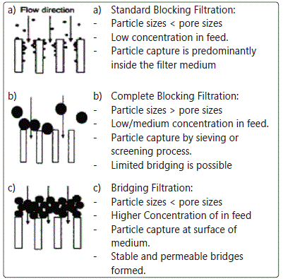
Figure 1: Mechanisms of filtration [25]
Similarly, the solid invasion into the porous formation can
be classified into three main types: surface bridging, shallow
plugging, and deep invasion. The fine solids penetrate into
the porous formation and eventually accumulate and block
the pore throats by forming an internal filter cake [26].
Minimizing formation damage
Though the accumulation of filter cake and filtrate
invasion is directly related to the formation damage, if the
drilling fluid is capable of forming an impermeable filter cake
opposite to the producing zone, it will reduce the filtration loss and hence the formation damage [7]. Since the initial
filtrate loss, known as the spurt loss, is usually the highest, the
formation of the impermeable filter cake has to take place
quickly. Moreover, the filter cake has to be thin in order to
avoid stuck pipe problems [7].
The formation of such filter cake should take place in the
near wellbore pores (i.e. an external filter cake) [26]. This will
help minimize formation damage by avoiding the formation
of an internal filter cake which is harder to remove [27]. Moreover, the external filter cake should be easily removed by
a suitable treatment or cleanup operation. These requirements
have led to the development of Drill-in-fluid, which is
commonly used in drilling the pay formation of most oil
reservoirs [28].
Drill-In Fluids
As mentioned previously, drill-in fluids are drilling fluids (either water or oil based) designed specifically for pay zone
drilling operations, thus drill-in fluids are expected to be nondamaging
to the producing formations. In other words, drillin
fluids should be designed in such a way that an impermeable
and thin external filter cake is formed which would resist the
invasion of either filtrate or fine solids. Moreover, conventional
drilling fluid additives need to be replaced with non-damaging
ones. For example, the use of bentonite, a conventional
rheology additive, is not accepted in the formulation of drillin
fluids. Instead, it is replaced with other non-damaging and
bio-derived additives such as starch and xanthan gum.
It is obvious that the size of the particles within a drilling
fluid slurry relative to the size of pores in the opposite
producing zone, is an important aspect with regards to the
formation damage. As mentioned previously, depending on
the relative size (bigger or smaller), invading particles can
either block or bridge the porous media. Therefore, controlling
the size of such particles is highly necessary for damage
control [23] [25]. Researchers have shown that the formation
of an impermeable and thin external filter cake can be
facilitated by the addition of properly sized bridging particles
to the drill-in fluids [27] [29] [30]. Bridging particles are solid
additives, used to bridge across the pore throats and hence
form a filter cake to prevent invasion of particles and liquids
[4].
Selection of bridging particles
The primary types of bridging particles used in the
industry are calcium carbonate and sodium chloride [29]. Different sizes and grades of each type are available as well. Even though calcium carbonate and sodium chloride can
both be used as drilling fluids bridging particles, they have
different properties as mentioned by Davidson and Stewart
[28]. For example, sodium chloride is water soluble, whereas
calcium carbonate is acid soluble. Therefore, residual filter
cakes formed by drilling fluids with sodium chloride are
treated and cleaned by using under-saturated brine. On the
contrary, residual filter cakes formed by drilling fluids with
calcium carbonate can be cleaned using acids. The cuttings
disposal from drilling fluids with sodium chloride always presents a higher polluting potential than cuttings from
drilling fluids with calcium carbonate [28]. Another significant
point is that the chemical driving force between an acid and
carbonate is much stronger than that between water and salt. This implies that over the same period of time, there will be
more complete dissolution of carbonate by acid than of salt
by water. Higher preference to calcium carbonate is evident, as it possesses proper mechanical and chemical stability and it
is highly acid soluble [26]. Such properties allow the formed
filter cake to have mechanical consistency, resistant to the
drilling impacts and high-pressure differentials, and allow for
better removal to recover the original permeability of the
reservoir rock. In cases when the use of acid based treatments
is not acceptable, or the well to be drilled is a water injector or
producer, sodium chloride has an advantage over calcium
carbonate. That is because; the injected or produced water is
expected to dissolve any residual filter cake [28]. The
aforementioned aspects have to be taken into consideration
in the selection of bridging particle type.
Selecting bridging particle size distribution
Selection of bridging particle size distribution needs
careful evaluation of the following:
Reservoir rock-pore size distribution
This is an important aspect that has to be carefully
considered in selecting the size distribution of the bridging
particles to be used in the drill-in fluids. It is a worth noting
that the size distribution has to be considered regardless of
the type of the bridging agent [28]. The first step in selecting
the bridging particle size distribution in drill-in fluids is to
determine the pore geometry and the petro-physical
characterization of the reservoir rock [29]. Various techniques
and analyses are available for reservoir rock characterization, and each possesses some advantages and limitations.
The most commonly laboratory based techniques of pore
system characterization in reservoir rocks, are thin-section
analysis, mercury injection, scanning electron microscopy (SEM) analysis and CT scanning techniques [30]. Below is a
comparison between the aforementioned techniques [30]:
-- Thin-sections analysis: it is inexpensive relative to
other methods and offers direct measurement of the
pore size. However, the measurement is two
dimensional only and it is operator dependent (i.e. Human error dependent). The detectable pore size
range using thin-section analysis is 2 to 5000 microns.
-- Mercury injection: it is less operator dependent than
thin section analysis. However, it may not detect the
largest pore sizes in many reservoir formations. The
detectable pore size range using mercury injection is
0.0025 to 100 microns.
-- SEM analysis: it is extremely practical to measure very
small pores (i.e. micro-porosity). However, it is less
practical to measure large pores due to high cost and
time. The detectable pore size range using SEM
analysis is 0.05 to 5000 microns.
-- CT scanning: it can evaluate the three-dimensionalpore geometry and pore size statistics. However, it is
difficult to encompass the entire range of pore sizes.
In the field scale, the Full-bore Formation Micro-Imager (FMI) allows much enhanced evaluation of complex reservoirs
by using micro-electrical arrays [31]. It enables an in-situ
description of the reservoir without having to resort to fullhole
coring over the entire zone of interest. The imaging tool
provides images of the borehole wall at a resolution of 0.2
inches. The borehole coverage of this new tool is 80% in an 8
inches borehole. Application of such tool include fracture
identification, analysis of small-scale sedimentological
features, evaluation of net pay in thinly bedded formations
and the identification of borehole irregularities.
Methods of bridging particles size distribution
Different approaches are followed to deduce the required
bridging particles size distribution in a given reservoir
condition. These approaches can be divided into two main
categories, Abram's Rule and the Ideal Packing Theory (IPT). It
is worth mentioning that the IPT has undergone continuous
improvement since it was first proposed. Though Abram's
Rule is still being applied, limitations within its applicability
have been recognized especially in carbonate reservoirs. Detailed view towards each of the aforementioned theories is
described below.
Abram's rule [32]
Abram's Rule states that muds with bridging particles
having median size equal or slightly greater than one-third of
the median pore size of the formation will caused damage
due to solid invasion which occurred to a depth of less than 1
inch. Such damage depth is normally penetrated by
perforations and does not significantly affect the injectivity or
productivity of the wells. The concentration of these bridging
particles must be at least 5% by volume of the total solids in
the final mud mix. The limitation of Abram's Rule is that it only
addresses the size of the particles required to initiate a bridge. That is, it does not provide an optimum size or state an ideal
packing sequence for minimizing fluid invasion and optimizing
formation sealing [29]. Moreover, Abram's Rule may be very
effective in homogenous formations; however, it is difficult to
maintain the optimum particle size distribution in
heterogeneous formations [33].
Abram's guidelines are still usable when little is known
about the pore size distribution in a particular reservoir [27]. In such cases, a wide range of bridging particles is added to
the drilling fluid in an attempt to provide a wide range of
bridging capabilities.
Ideal Packing Theory
Unlike Abram's Rule, the Ideal Packing Theory (IPT) is
concerned with the packing sequence for formulating a
minimally non-damaging fluid [34]. It provides the full range
of particle size distribution required to effectively seal all the
pores, including those created by bridging agents. This
subsequent layering of bridging agents results in a tighter and
less invading filter cake [29].
The first form of IPT described the correlation between
particle size distributions using a relationship between the
cumulative volume percentage (CV) and the particle diameter
d [35]. The relationship was given as, where is a variable
exponent. With regards to this relationship, the IPT suggests
that there is a value of at which the size distribution tends to
result in bridging particles forming a filter cake with minimal
voidage [34]. The maximum packing density obtained
following this relationship was when lays between 0.5 and
0.67.
It is a worth noting that different values have different
meanings. If is equal to 1, a linear relationship is present, meaning there is an equal volume of particles of each size. If
is less than 1, a higher proportion of small particles is present. If is larger than 1, a higher proportion of large particles are
present. Too high concentration of small particles would
displace and wedge the larger particles apart and therefore
interfere with packing efficiency. On the other hand, too high
concentration of larger particles would leave voids that are
not sufficiently plugged with small particles. Therefore, it may
be expected that there is an optimum value of or at least an
optimum range [25].
The literature includes various suggestions with regards
to the IPT, some important ones with the optimum value of
are mentioned below:
-- Furnas [36] suggested that the optimum value of is a
function of several factors such as the size distribution, shape, packing structure randomness. Therefore, there is no single grading curve sufficient for all types
of material, and hence, will need to be experimentally
determined.
-- Bo et al [37]. showed that for particles of similar size
limits, the porosity of packed beads decreases as the
value of approaches 1.
-- Dick et al [29]. suggested that the ideal packing
occurs when the cumulative volume percentage vs. particle size diameter raised to the power of 0.5 forms
a straight line relationship.
-- Chellappah and Aston [25], showed from their
experimental results that the optimum value of to be
closer to 1 than 0.5.
In Ideal Packing Theory, it is desirable to select a particle
size distribution that will quickly bridge the largest pore
openings, the medium pore openings and a smaller pore size
fraction. These targets fractions are generally based on the
D90, D50 and D10 of the reservoir pore throat distribution
[27], where DA is the particle size at which the percentage of
total solids (by volume) are smaller than A. No additional
improvement can be observed when more than three varieties
of bridging agents are used [33]. On the contrary, it was
proven that when sufficient pore data is known, matching the
pore size distribution with additional target fractions, D75 and
D25, would result in higher return permeability [27].
Other Drill-in Fluids Additives
Drill-in fluids are generally water-based muds which contain a combination of additives. This combination is made
of a viscosifier, fluid loss additive and sized particles (i.e. bridging particles) [37]. Xanthan gum is used as a viscosifier
while modified starches and cellulose polymers are used for
filtration loss [38]. Xanthan gum and modified starch have
some advantages over the conventional mud additives. Conventional mud additives such as bentonite should be
avoided as they were proved to cause damage to the
formations ultimate performance. The following sections shed
light on the use of bentonite and similar compounds
compared to the use of degradable polymers.
Disadvantages of Bentonite and Other insoluble rheology
controllers
Bentonite is a naturally-occurring clay material, which is
composed mainly of sodium montmorillonite4.Bentonite
swells to many times its dry volume when hydrated by water. Therefore, it forms a viscous fluid with high gel strength
making it an excellent additive when used as a viscosifier as
well as it works well as a sealant. However, the filter cake
formed by bentonite is found to be highly detrimental to the
formation performance. The main reason behind this effect is
that, once bentonite is hydrated and forms the protective
mud cake it cannot be easily removed. As mentioned
previously, a desirable mud cake has to be easily removable in
order to restore the well productivity/injectivity. In case of
bentonite, this requirement is not satisfied. Consequently, the
only effective way to restore the well is by physically removing
the bentonite from the well. This is usually done through
mechanical or hydraulic agitation, which is not effective
enough in most wells. Moreover, due to the swelling effect, a
very limited open area may be available for a chemical
injection or mechanical agitation especially in horizontal wells. This results in an inefficient removal of the filter cake, leaving
the well performance much lower than expected [39]. In order
to overcome some of the disadvantages of bentonite, Nano-
Enhanced drilling fluids are designed which demonstrated
superior lubricity and hole cleaning properties while retaining
suitable viscosity and density [40], however the post-drilling
hole clean up still remains an issue.
To overcome the wellbore clean up issues with bentonite
as rheology controller, degradable polymers and related
rheology controlling additives; such as xanthan gum, modified
starch and modified cellulose products (polyanioic cellulose
being the most preffered one) are in use as viscosifier and
rheology controller. They provide similar characteristics as the
conventional mud additives, however, unlike the conventional
additives, they are able to breakdown naturally within a few
days. If necessary, the break down process may be accelerated
to a few hours through the use of specific enzymes. Therefore, biopolymers are much less likely to cause formation damage
and can provide as much as 40 times the flow rate of wells
drilled with Bentonite [39]. On the other hand, biopolymers
cost much more than conventional bentonite. However, when
considering the ultimate well performance provided by their
use, the initial cost of biopolymers is more than compensated
[39].
Drilling Through Depleted & Under-pressure Reservoirs
Drilling through depleted and under-pressured reservoirs
is quiet challenging due to the technical and economic
problems that often make it unprofitable to further develop
such fields [41]. The most common problems related to such
type of drilling are the uncontrollable losses of mud or mud
filtrate and differential sticking of drill string. In order to
overcome such problems, APHRON drilling fluids were
introduced. APHRON drilling fluids refer to a special type of
drilling fluids which are designed to be used for drilling
depleted reservoirs and other under-pressured zones by
controlling losses through high-permeability sands while
stabilizing the pressured shales or other formations [41]. APHRON drilling fluids are highly shear-thinning water base
fluids containing stabilized air-filled bubbles and are able to
seal loss zones with non-permanent formation damage [42]. The air that is used to generate APHRONs is usually
incorporated into the fluid with conventional mud mixing
equipment at ambient pressures. As a result, the cost and
safety concerns associated with air or foam drilling are
reduced. Although the performance of APHRONS in the fields
as cost effective alternative to under balance drilling is well
documented, the mechanisms through which they work is still
questionable [42]. Below is the survey findings that was
conducted under the auspices of the U.S. Department of
Energy in order to develop further understanding of APHRONs
role. The findings of this study included [41]:
-- APHRONs can survive elevated pressures for a much
longer time than conventional bubbles.
-- In loss zones, APHRONs can migrate faster than the
base liquid and concentrate at the fluid front, and
hence, building an internal seal in the pore network
of the rock.
-- The APHRONs are able to reduce the rate of invasion
through the aid of a micro gel network formed by
particulates in the pore network of the rock.
-- As the fluid slows, the low shear-rate viscosity of the
base fluid enables the fluid to generate high viscosity
rapidly.
-- Bridging and formation of a low-permeability external
filter cake also occur to ultimately reduce the rate of
invasion to that of ordinary fluid loss.
-- APHRONs have very little attraction for each other or
for mineral surfaces. Consequently, they do not
readily coalesce nor stick easily to the pore walls. This
is important when production starts.
The combination of the above features is expected to
result in low formation damage and minimal requirements for
cleanup [42].
Fluid Invasion into the formation
APHRON drilling fluids have proven the ability to seal-off
rocks as permeable as 80 Darcy, as static linear leak-off tests
have demonstrated [42].
The following figure shows the role of APHRON drilling fluids when used with Aloxite cores with permeabilities of 0.75
to 10 Darcy.
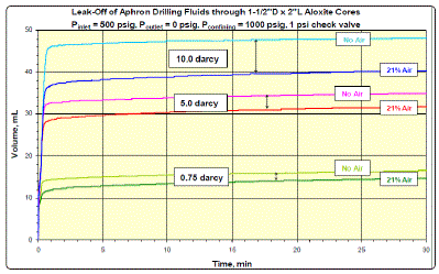
Figure 2: APHRON Drilling Fluids sealing ability with high permeability formations [42]
Figure2 demonstrates that for each curve, there is a high rate spurt loss stage, at which the volume increases linearly with time. APHRON drilling fluids contain low levels of particulates that combine to form an external filter cake and shut down whole mud loss. As shown in figure 2, APHRONs are able to reduce the spurt loss below the levels afforded by the base fluid. Surprisingly, at low pressures, APHRONs can form an internal seal, while becoming an integral part of the filter cake [42].
APHRONs-related Formation Damage
In order to confirm the non-damaging ability of APHRONs, several return permeability tests were conducted using Berea
sandstone core plugs along with APHRONs, a well-constructed
reservoir mud and Hydroxyethyl cellulose mud [42]. The
following figure shows the results of these tests:
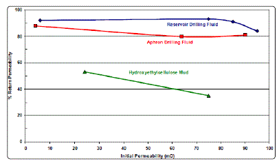
Figure 3: AReturn permeability of APHRONs vs reservoir mud & Hydroxyethyl cellulose mud [42]
Figure 3 shows that the formation damage potential of
APHRONs is quiet low and is close to that of a well-constructed
reservoir drilling mud [42].
Compatibility with formations and produced fluids
As mentioned previously, APHRONs resist coalescence
and aggregation, and they have the ability to remain as
discrete bubbles in the circulating fluid during a lost circulation
event [43]. APHRON's low wettability implies an easy cleanup
of the pay zone post to drilling operations. By examining the wetting behavior of oil and APHRONs, it was concluded that
whether the oil is applied to the drilling fluid or the fluid is
applied to the oil (see Fig 4), the applied phase spreads over
the substrate phase, indicating a very low contact angle. Therefore, APHRONs and oil are highly compatible phase [43].
The following figure shows the contact angle in both cases.
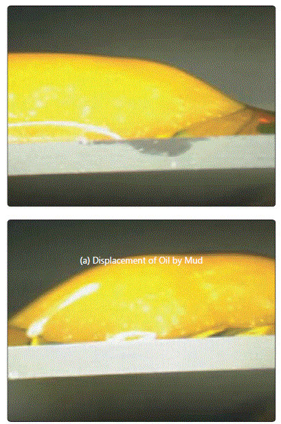
Figure 4: APHRON drilling fluids and crude oils are very compatible as shown by the low contact angles [43].
Application of Nanotechnology in Drilling Fluid
Nanotechnology has been applied in the oil industry after
being proven successes in a variety of fields such as electronics, material composites and medical goods. In order for
nanotechnology to be successfully applied in drilling fluids, it
must satisfy two main conditions which are [44]:
-- Provide what conventional technologies are not
capable of.
-- Have advantages over a colloidal or micro-sized method.
Nano-particles as an additive in drilling fluids has been
studied for several years especially in the fields of rheology, fluid loss, system enhancement or shale stability [45], which
are discussed below.
Rheology and Fluid Loss Control
One of the important properties of nanomaterials is their strong particle-particle interaction, making them high
potential viscosifying additives. For example, addition of
graphene oxide (GO) to a water base mud containing
bentonite and barite has shown a quiet substantial effect
when added only 2 lb/bbl of GO in the mud. Table-1 shows
the effect of such addition.
Graphene oxide sheet-like structure has attracted attention
to the researchers due to its applicability to be used as a fluid
loss controller. The results of adding graphene oxide to a fresh
water drilling system has proven effective impact on both
rheology and fluid loss [46]. Amazingly, adding 1 lb/bbl of
graphene oxide functioned as effective as adding 5lb/bbl of
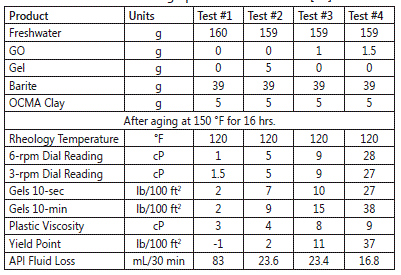
Table 1: APHRON drilling fluids and crude oils are very compatible as shown by the low contact angles [43].
conventional gel. Table-2 shows the effect of adding graphene oxide on fresh water base mud.
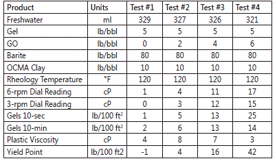
Table 2: fluid loss effect of adding graphene oxide [45]
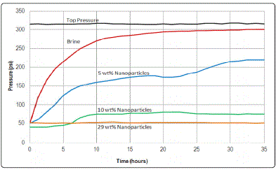
Figure 5: Sealing performance of Nano silica on shale [47].
Drilling deep reservoirs generate technical challenges due to their extremely high pressures and temperatures, which may go up to 1400 bar and 300°C respectively. It is difficult for most conventional mud additives to withstand such extreme condition, and they undergo thermal degradation, which results in loss of the required mud properties, such as rheological properties. This has motivated huge research interest and several laboratory level successes are reported. Formate based brines are in the market for quite some time which, uses sodium, potassium and cesium formate brines in drilling HP-HT wells and an established field proven water based drilling fluid, though cesium formate is cost ineffective and rarely in use [48] [49]. A new water based mud is developed with manganese tetroxide as the weighting agent modified poly-acrylics and polyvinyl-pyrolidone, whose properties are thermally stable up to 180oC [50]. Water base mud containing Multiwall Carbon Nanotubes (MWCNTs) are tested up to 500 °F temperature and up to 25,000 psi pressure and compared with high temperature stable oil base mud. The rheological properties of the new mud offered belter environmental acceptance with improved rheological properties [50].
Conclusion
In conclusion, the success of any drilling operation is
strongly related to the performance of the drilling fluid. The
drilling fluid performance is a function of several factors such
as drilling-related formation damage and wellbore. However, a high performance drilling fluid should also comply with the
general concerns and requirements of the industry. Therefore, the evaluation of any drilling fluid is based not only on its
performance, but also on its cost and its effect on health, safety and environment. In general, there isn't (so far) such an
ultimate type of drilling fluid that can fulfill all the industry
requirements. Until then, the drilling fluids will continue to
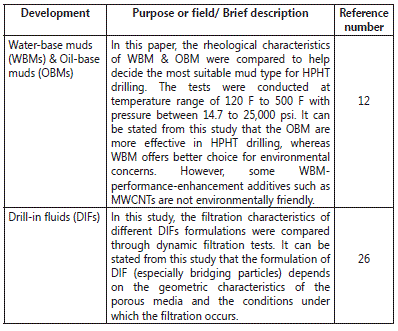
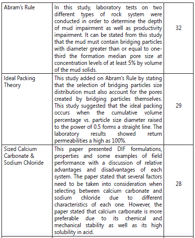
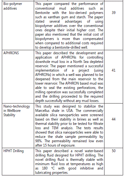
develop with new types and formulations. The review work is
being summarized in the table below, which may serve as a
ready reference for a specific type of drilling fluid requirement.
References
- Gray GR, Darley HCH, Rogers WF. Composition and Properties of Oil Well Fluids. Houston, Texas: Gulf Publishing Company. 1981; ISBN-10: 0872011291.
- Baker H. Drilling Fluids Reference Manual, 2006.
- Fink J. Petroleum Engineer's Guide to Oil Field Chemicals and Fluids. Waltham, Massachusetts: Gulf Professional Publishing. 2011; ISBN: 9780128037348
- Schlumberger Oil Field Glossary, 2015.
- Rogers WF. Composition and Properties of Oil Well Drilling Fluids. Houston, Texas. Gulf Publishing Company. 1963; ISBN-13: 978-0872011298.
- API Recommended Practice 13B-2: Recommended Practice for Field Testing Oil-Based Drilling Fluids.
- Chilingarian GV, Vorabutr P. Drilling and Drilling Fluids. Amsterdam, Netherlands. Elsevier. 1983; ISBN-10: 0444421777
- Lyons WC, Gary J, Michael D. Standard Handbook of Petroleum and Natural Gas Engineering. Massachusetts, USA. Gulf Professional Publishing. 2015; ISBN: 9780123838469.
- ASME Shale Shaker Committee, Drilling Fluids Processing Hand Book, Massachusetts, USA: Gulf Professional Publishing. 2005; 9780750677752.
- Guichard B, Wood B, Vongphouthone P. Fluid Loss reducer for high temperature high pressure water based-mud application. 2008.
- Bourgoyne AT, Millheim KK, Chenevert ME, Young FS. Applied Drilling Engineering. USA. 1986; ISBN: 978-1-55563-001-
- Abduoa M, Dahabb A, Abusedaa H, Elhossieny M. Comparative study of using Water-Based mud containing Multiwall Carbon Nanotubes versus Oil- Based mud in HPHT fields. Egyptian Journal of Petroleum, 2016; 25(4): 459- 464. doi: 10.1016/j.ejpe.2015.10.008
- Henaut I, Pasquier D, Rovinetti S, Espagne B. HP-HT Drilling Mud Based on Environmentally-Friendly Fluorinated Chemicals. Oil Gas Sci. Technol. 2016; 70(6): 917-930. doi: 10.2516/ogst/2014047
- Dows JD. Formate brines: novel drilling and completion fluids for demanding environments. SPE Paper 25177, presented at International Symposium on oilfield chemistry, New-Orleans, Louisiana, USA 1993.
- Gallino G, Guarneri A, Maglione R, Nunzi P, Xiao L. New formulations of potassium acetate and potassium formate polymer muds greatly improve drilling and waste disposal operations in south Italy. SPE Paper 37471, presented at SPE Production Operations Symposium, Oklahoma City, USA 1997.
- Simpson MA, Al-Reda S, Foreman D, Guzman J, Al-Fawzy M, Vice P. Application and recycling of sodium and potassium formate brine drilling fluids for Ghawar field HT gas wells. OTC 19801, presented at Offshore Technology Conference, Houston, Texas, USA 2012.
- Patel AD, Stamatakis E, Davis E. Shale hydration inhibition agent and method of use. US patent 6 247 543. 2001.
- Dardira M, Ibrahimea S, Solimanb M, Desoukya S, Hafiza A. Preparation and evaluation of some ester amides as synthetic based drilling fluids. Egyptian Journal of Petroleum. 2014; 23: 35-43.
- Okorie E, Agwu A, Anietie N, Francis D. A Comparative Study of Diesel Oil and Soybean Oil as Oil-Based Drilling Mud. Journal of Petroleum Engineering. 2015; ID 828451: 10. doi:10.1155/2015/828451
- Yan J, Wang F, Jiang G, Fan W, Su C. A Solid emulsifier to improve the performance of oil-in water drilling fluids. SPE Paper 37267. Presented at the International symposium on Oilfield Chemistry, Houston, TX, USA 1997.
- Cox M. Advances in high-performance drilling fluids enhance wellbore strength, help curb loss. 2010.
- Advantages and Disadvantages of Oil Based Mud.
- Mohamed M. Engineered Particle Size Distribution While Drilling Helped Minimizing Wellbore Damage in Sandstone Reservoirs. SPE Paper 141752. Presented at the SPE Middle East Oil and Gas Show and Conference, Manama, Bahrain 2011.
- Fallah H, Sheydai S. Drilling Operation and Formation Damage. Open Journal of Fluid Dynamics. 2013; 3(2): 38-43. doi: 10.4236/ojfd.2013.32005
- Chellappah K, Aston M. A New Outlook on the Ideal Packing Theory for Bridging Solids. SPE Paper 151636. Presented at the SPE International Symposium and Exhibition on Formation Damage Control Lafayette, Louisiana, USA 2012.
- Cargnel R, Luzardo J. Particle Size Distribution Selection of CaCO3 in Drill-In Fluids: Theory and Applications. SPE 53937. Presented at the SPE Latin American and Caribbean Petroleum Engineering Conference, Caracas, Venezuela 1999.
- Vickers S, Cowie M, Jones, T, Allan, J. A new methodology that surpasses current bridging theories to efficiently seal a varied pore throat distribution as found in natural reservoir formations. Wiertnictwo Nafta Gaz. 2006; R.23/1: 501-515.
- Davidson E, Stewart S. Open Hole Completions: Drilling Fluid Selection. SPE 39284. Presented at the SPE/IADC Middle East Drilling Technology Conference, Bahrain 1997.
- Dick M, Heinz T, Svoboda C, Aston M. Optimizing the Selection of Bridging Particles for Reservoir Drilling Fluids. SPE 58793. Presented at the SPE International Symposium on Formation Damage, Lafayette, Louisiana 2000.
- He W, Stephens M. Bridging Particle Size Distribution in Drilling Fluid and Formation Damage. SPE 143497. Presented at the SPE European Formation Damage Conference, Noordwijk, The Netherlands 2011.
- Safinya K, Le Lan P, Villegas M, Cheung P. Improved Formation Imaging With Extended Micro electrical Arrays. SPE 22726. Presented at the 66th Annual Technical Conference and Exhibition of the Society of Petroleum Engineers, Dallas, TX, USA 1991.
- Abrams A. Mud Design to Minimize Rock Impairment Due To Particle Invasion. SPE Paper. 1977.
- Jienian Y, Feng W. Design of Drill-in Fluids by optimizing selection of bridging particles. SPE 104131. Presented at the SPE International Oil & Gas Conference and Exhibition, Beijing, China 2006.
- Kumar P, Vikas M, Saxena V. Emulsion Based Drilling Fluids: An Overview. International Journal of ChemTech Research. 2014; 6(4): 2306-315.
- Andreasen A, Anderson J. Koll Z. 1930; 50:217.
- Furnas C. Grading aggregates 1- mathematical relations for beds of broken solids of maximum density. Ind. Eng. Chem. 2006; 23(9): 1052-1058. doi: 10.1021/ie50261a017
- Al-Otaibi M, Nasr-El-Din H, Al Moajil A. In-Situ Acid System to Clean Up Drill-in Fluid Damage in High Temperature Gas Wells. SPE Paper 103846. Presented at the IADC/SPE Asia Pacific Drilling Technology Conference and Exhibition, Bangkok, Thailand 2006.
- Ghosh B, Mehtar MA, Ghosh D, Chaudhuri B. Derivation of kinetic rate constant of enzyme-buffer mud cake clean up systems - Laboratory investigation and verification in high temperature fractured carbonate reservoir. SPE Paper 161643. Presented at the Abu Dhabi International Petroleum Exhibition & Conference, Abu Dhabi, UAE 2012.
- Why Bentonite Hurts Well Production: The Case for Biopolymer Drilling Fluid.
- Abdo J, Haneef M. Pioneering Approach to Overcome Uncompromising Drilling Problems. Energy Resources Technology. 2011; 134(1): 6. doi: 10.1115/1.4005244
- Craig C, Adrian, P, Nam C, Ivan C, Maikranz S, Nouris R. Aphron-based Drilling Fluid: Novel Technology for Drilling Depleted Formations in the North Sea. SPE Paper 79840. Presented at the SPE/IADC Drilling Conference, Amesterdam, The Netherlands 2003.
- Belkin A, Irving M, O'Connor R, Fosdick M, Hoff T, Growcock F. How Aphron Drilling Fluids Work. SPE 96145. Presented at the SPE Annual Technical Conference and Exhibition, Dallas, Texas, USA 2005.
- Growcock F, Belkin, A, Fosdick M, Irving M, O'Connor B. Recent advances in Aphron Drilling-Fluid Technology. SPE Drilling & Completion. 2007; 22(2): 74-80. doi: 10.2118/97982-PA
- Hoelscher K, Stefano D, Riley G, Young S. Application of Nanotechnology in Drilling Fluids. SPE 157031. Presented at the SPE International Oilfield Nanotechnology Conference, Noordwijk, The Netherlands 2012.
- Friedheim J, Young S, Stefano GD, Lee J, Guo Q. Nanotechnology for Oilfield Applications. SPE 183301. Presented at the SPE International Oilfield Nanotechnology Conference, Noordwijk, The Netherlands 2012.
- Kosynkin D, Ceriotti G, Wilson G, Lomeda K, Scoresone J, Patel J, Friedheim, A, Tour J. Graphene Oxide as a high performance Fluid-Loss Control Additive in Water-Based Drilling Fluids. ACS Applied Materials & Interfaces. 2011; 4: 222-27. doi: 10.1021/am2012799
- Sensory T, Chenvert M, Sharma M. Minimizing Water Invasion in Shales Using Nanoparticles. SPE 124429. Presented at the SPE Annual Technical Conference, New Orleans, USA 2009.
- Dows JD. Formate brines: novel drilling and completion fluids for demanding environments. SPE Paper 25177. Presented at the International Symposium on oilfield chemistry, New-Orleans, Louisiana, USA 1993.
- Gallino G, Guarneri A, Maglione R, Nunzi P, Xiao L. New formulations of potassium acetate and potassium formate polymer muds greatly improve drilling and waste disposal operations in south Italy. SPE Paper 37471. Presented at the SPE Production Operations Symposium, Oklahoma City, USA 1997.
- Tehrani MA, Popplestone A, Guarneri A, Carminati S. Water-based drilling fluid for HP/HT applications. SPE Paper 105485. Presented at the International Symposium on oilfield chemistry, Houston, Texas, USA 2007.

