Research Article
Hypersonic Boundary Layer Flow at a Stagnation Point with Applied Magnetic Field and Vectored Surface Mass Transfer
1Professor of Aerospace Engineering, Ph.D., Department of Aeronautics and Astronautics, Air Force Institute of Technology, Wright
Patterson Air Force Base, USA
2Research Scientist (Retired), Ph.D., Department of Mathematics, Indian Institute of Science, India
*Corresponding author: Rama Subba Reddy Gorla, Professor of Aerospace Engineering, Ph.D. Department of Aeronautics and Astronautics, Air Force Institute of Technology, Wright Patterson Air Force Base, Dayton, Ohio 45433, USA, E-mail: Rama.Gorla@afit.edu
Received: October 25, 2023 Accepted: November 20, 2023 Published: December 2, 2023
Citation:: Gorla RSR, Kumari M. Hypersonic Boundary Layer Flow at a Stagnation Point with Applied Magnetic Field and Vectored Surface Mass Transfer. Int J Aeronaut Aerosp Eng. 2023; 3(1): 86-93. doi: 10.18689/ijae-1000112
Copyright: © 2023 The Author(s). This work is licensed under a Creative Commons Attribution 4.0 International License, which permits unrestricted use, distribution, and reproduction in any medium, provided the original work is properly cited.
Abstract
A boundary layer analysis is presented for hypersonic flow in the vicinity of a stagnation point region of a blunt body under isothermal and adiabatic boundary conditions. Consideration is given to variable properties of air. It has been shown that surface drag and heat transfer rates may be controlled by applying magnetic field and vectored surface mass transfer. The range of Mach numbers considered is 2.5 to 10. As the magnetic field strength M increases, friction factor and heat transfer rate (in the case of isothermal surface) or surface temperature (in the case of adiabatic surface) increase. Friction factor and surface temperature (in the case of adiabatic surface) can be reduced by applying vectored surface mass transfer.
Keywords: Hypersonic; compressible flow; boundary layer; magnetic field; vectored surface mass transfer
Introduction
Aerodynamic heating is the heating of a surface due to flow of air at high speed. The kinetic energy of the air will be converted to thermal energy within the boundary layer. Prediction of the heat transfer rate to the surface at high Mach number flows is crucial to the design of thermal protection system. Tauber and Mennes (1986) made engineering estimates of the aerodynamic heating to an aerospace plane. According to their estimates, aerodynamic heating during ascent (about 650 W/cm2) dominates the design of the vehicle.
At hypersonic speeds, air cannot be considered as a simple mixture of diatomic oxygen and nitrogen. At a Mach number 20, the air temperature behind a normal shock wave for a blunt body can reach 6500 K during re-entry. The air undergoes considerable change in composition. Dissociation of oxygen and nitrogen occurs. The air becomes electrically conductive at high temperatures and can interfere with radio wave transmission and reception. The magnetic field can alter the drag and heat transfer characteristics.
Klopfer and Yee (1988) investigated viscous hypersonic flow on a blunt body. Hoffmann et al. (1991) discussed the difficulties in predicting heat transfer rates for high speed flows. Qu et al. (2017) presented an analysis for hypersonic heating. All these studies assumed a constant value of specific heat of air. Zhang et al. (2017) provided a turbulence model for aero thermal prediction. Liu and Cao (2017) studied the heat transfer in hypersonic boundary layer over a flat plate by taking into account of variable properties.
The flow in the vicinity of a stagnation point is always laminar. The present analysis is valid for stagnation point region. It is expected that far away downstream from the stagnation point, the flow undergoes transition due to finite disturbances and finally reaches fully established turbulent condition. If the initial amplitude of the disturbance is small, Tollmien-Schlichting (TS) waves will be observed. The two dimensional waves then develop into growing three dimensional structures by secondary instability process. These develop nonlinearly into lambda (Λ) - shaped structures, known as lambda vortices and the fluid velocity changes rapidly. When amplitudes reach large values, there will be a rapid breakdown to short scaled structures known as spikes. This will be followed by the onset of random behavior and the eventual development of a turbulent flow. This is often through the growth of isolated patches of turbulence or spots from the regions of the spikes that merge as they travel downstream.
The friction factor and heat transfer rate in turbulent flow will be higher than laminar flow conditions, reaching about 50% more. The present proposed methodology of using magnetic forces and vectored surface mass transfer has the potential of reduction of friction factor and heat transfer and hence delay the transition to turbulence. Turbulent boundary layers can be relaminarized by creating favorable pressure gradient by adjusting the body contour. We make brief comments on relaminarization here.
Wall-bounded turbulence remains one of the least understood phenomena in fluid mechanics, despite its significance in many engineering fields. For example, approximately 50% to 80% of the total energy expenditure of commercial airplanes and container ships is used to overcome the turbulent frictional drag. The turbulent motions generate large skin friction on the surface of the spacecraft, and dissipate significant amount of energy through the downward turbulent energy cascade. In contrast, a relaminarized turbulent boundary layer (TBL) generates much reduced wall shear stress as discussed by Mukund et al. (2006), which is of great interest to both scientists and engineers. TBLs are commonly relaminarized when imposed with a strong favorable pressure gradient as discussed by Narasimha and Sreenivasan (1979). The favorable pressure gradient accelerates the bulk flow forward, which stabilizes the TBL by reducing the turbulent production while increasing the turbulent dissipation. Consequently, the wall shear stress drops over certain developing distance. To reduce the skin friction of wall-bounded turbulent flows, Wang and Gharib (2021) recently proposed a dynamic free-slip boundary method, which can be easily implemented to achieve significant wall shear stress reduction (by more than 40%).
The present work is undertaken in order to study the effect of applied magnetic field and vectored surface mass transfer in the case of hypersonic flow at a stagnation point. The properties of air are assumed to be temperature-dependent. Consideration is given to the application of transverse magnetic field in high speed aerodynamics where the air is ionized and changing the velocity and temperature fields as well as the drag and surface heat transfer rates. By applying magnetic field, one can control and reduce the drag and surface heat transfer rates. Such a mechanism is of extreme importance for flow over hypersonic vehicles. Rossow (1957) was the first one to analyze the effect of magnetic field in the case of incompressible boundary layer flow. The use of vectored surface mass transfer is another mechanism to reduce surface heat transfer rate and finds application in boundary layer control on aerodynamic vehicles, film and transpiration cooling of rocket engines, turbomachinery blades etc. Gorla (1977) studied the effect of vectored surface mass transfer in plane wall jet flows.
Governing Equations
We consider the laminar, hypersonic boundary layer flow of an electrically conducting viscous fluid at a stagnation point. An applied magnetic field B0 is imposed on the boundary layer. Blunt bodies generate strong shock waves. There is entropy change across the shock wave. The flow before the shock and external flow to the boundary layer after the shock can be assumed isentropic. We will consider both isothermal and adiabatic boundary conditions for the stagnation region. We consider variable properties and include vectored surface mass transfer. The governing boundary layer equations may be written as:
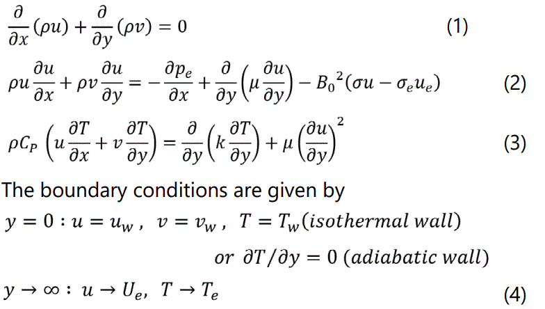
In the previous equations, x and y are the distances measured along and perpendicular to the streamwise direction and u and v are the velocity components in the corresponding directions. Cp is the specific heat; k the thermal conductivity; ρ the density; μ the viscosity; σ the electrical conductivity and B0 is the magnetic field strength.
Proceeding with the analysis, we define the following transformations:
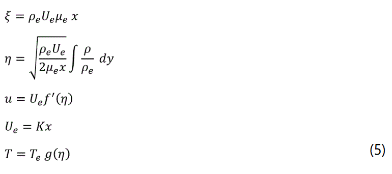
Here, cm and ck are chosen the same as Liu and Cao (2017). (12)

When the temperature range is from 600 K to 3500 K, the molecular vibration degrees of freedom of Oxygen and Nitrogen molecules in the air are excited and the specific enthalpy can be expressed following Jia and Cao (2010) as:

where R represents the gas constant and Tve denotes the vibration eigen temperature.
At high temperatures, the Oxygen and Nitrogen molecules are excited to the vibrational mode. We assume that Tve = 3030 K following Jia and Cao (2010)
The specific heat Cp may be written as

The transformed boundary conditions may be written as (isothermal wall); g′(0)=0 (adiabatic wall)

The local wall shear stress is given by

We define
The local friction factor may be written as

For the isothermal wall case, the local heat flux can be written as

In the previous equation, qw < 0 indicates heat transferred to the surface.The local heat transfer coefficient is given by

The local Nusselt number becomes


Results and Discussion
Equations (6) and (7) are solved numerically using the implicit finite difference method, Keller box method (Keller and Cebeci 1971).
Isothermal Wall Case:
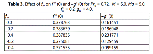
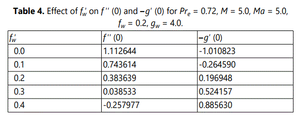
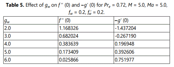
Tables 1-5 show the numerical results for f ′′ (0) and g′ (0) with M, Ma, fw, fw′ and gw are prescribable parameters.
Table 1. shows that as the magnetic parameter M increases, the wall shear stress decreases and the surface heat transfer rate increases. This suggests that the magnetic force can be used to cool the surface at high Mach number applications.
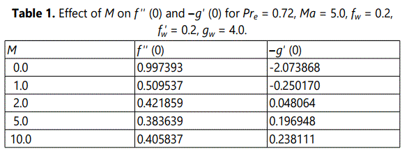
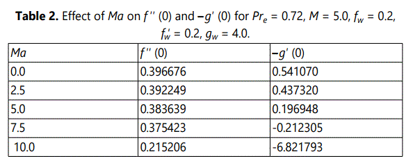
Table 2. shows that as the Mach number Ma increases, the wall shear stress and the surface heat transfer rate decrease. Values of Ma above 5, corresponding to hypersonic speeds, produce wall heating instead of wall cooling. This is due to the intense viscous dissipation at high Mach numbers. Table 3 indicates that wall blowing ( fw > 0) results in increased wall shear stress and surface heat transfer rate. Wall suction ( fw < 0) produces reduced wall shear stress and heat transfer rate. Table 4 shows that the downstream vectored surface mass transfer reduces wall shear stress and heat transfer rates.
Table 5 shows the effect of the value of surface temperature gw on wall shear stress and heat transfer rate. As gw increases, the wall shear stress decreases and heat transfer rate increases.
Figures 1 and 2 shows the velocity and temperature distributions within the boundary layer for varying values of the magnetic field strength.
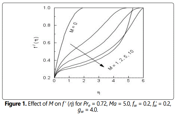
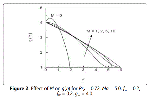
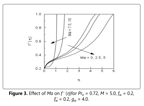
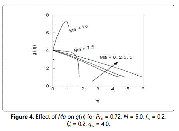
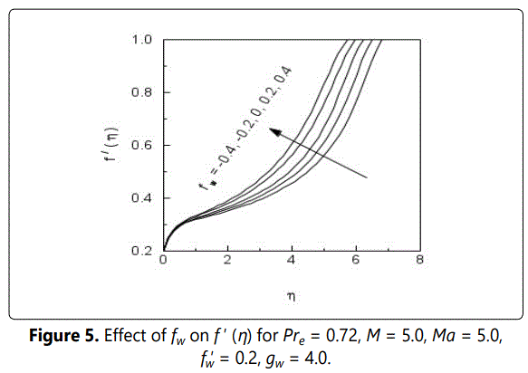
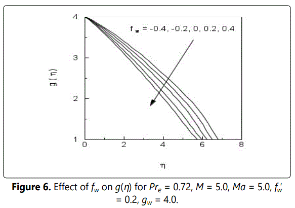
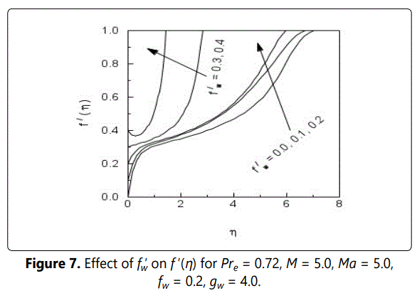
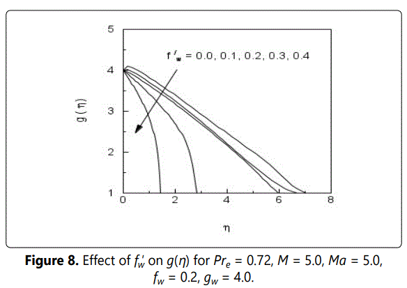
As the value of M increases, both velocity and temperature decrease within the boundary layer. Figures 3 and 4 show the effect of Mach number Ma on the velocity and temperature distributions within the boundary layer. As the Mach number exceeds a value of 5, the boundary layer thickness becomes very small and the flow “wraps around” close to the surface. Figures 5 and 6 show that as fw increases, the boundary layer thickness tends to reduce. The velocity at a distance normal to the surface increases whereas the temperature reduces. Figures 7 and 8 show that as fw′ increases, the boundary layer thickness tends to reduce. The velocity at a distance normal to the surface increases whereas the temperature reduces.
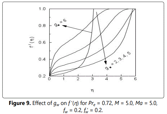
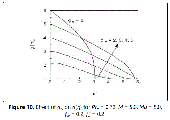
Figures 9 and 10 display result for the effect of wall temperature gw on the velocity and temperature profiles. As gw increases, the boundary layer thickness reduces. The velocity at a distance normal to the surface decreases whereas the temperature increases.
Adiabatic Wall Case:
Tables 6-9 show the numerical results for f ′′ (0) and g(0) with M, M, fw and fw′ are prescribable parameters.
Table 6. shows that as the magnetic parameter M increases, the wall shear stress increases and the surface temperature decreases.
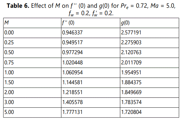
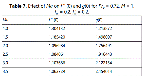
Table 7. shows that as the Mach number Ma increases, the wall shear stress decreases and the surface temperature increases. This is due to the intense viscous dissipation at high Mach numbers.
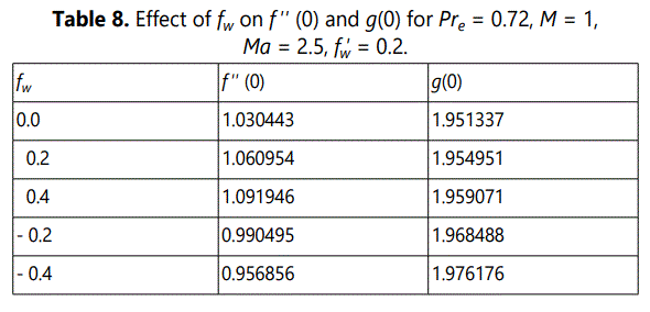
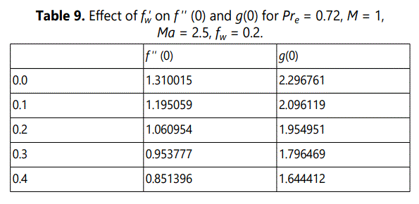
Table 8 indicates that wall blowing ( fw > 0) results in increased wall shear stress and surface temperature. Wall suction ( fw < 0) produces reduced wall shear stress and increased surface temperature. Table 9 shows that the downstream vectored surface mass transfer reduces wall shear stress and surface temperature.
Figures 11 and 12 show the velocity and temperature distributions within the boundary layer for varying values of the magnetic field strength.
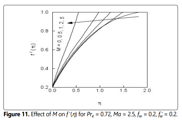
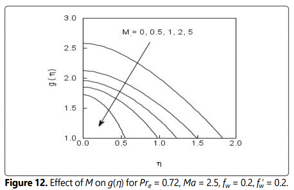
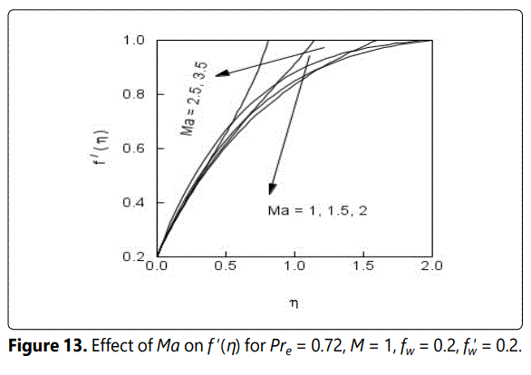
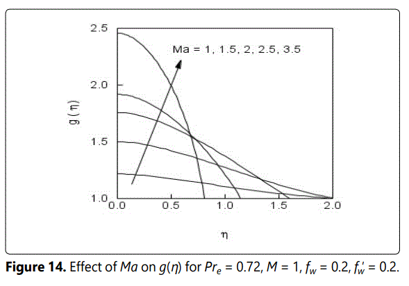
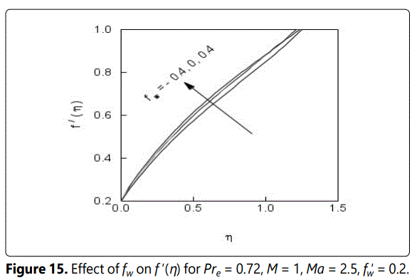
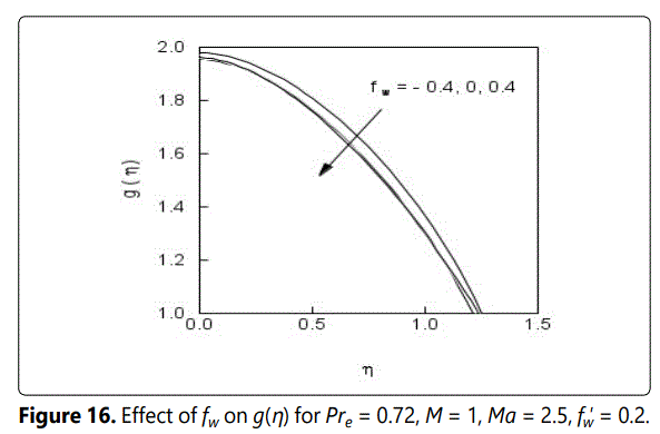
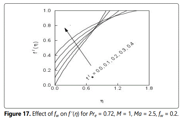
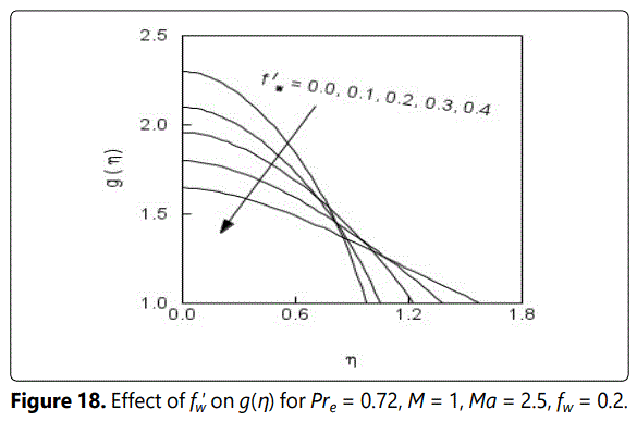
As the value of M increases, both velocity and temperature increase within the boundary layer. Figures 13 and 14 show the effect of Mach number Ma on the velocity and temperature distributions within the boundary layer. As the Mach number exceeds a value of 5, the boundary layer thickness becomes very small and the flow “wraps around” close to the surface. Figures 15 and 16 show that as fw increases, the boundary layer thickness tends to reduce. The velocity at a distance normal to the surface increases whereas the temperature reduces. Figures 17 and 18 show that as fw′ increases, the boundary layer thickness tends to reduce. The velocity in the boundary layer increases and surface temperature decreases as fw′ increases.
Concluding Remarks
In this paper, a boundary layer analysis is presented for laminar, hypersonic flow at a stagnation point. Consideration is given to variable properties of air. It is shown that surface drag and heat transfer rates may be controlled by applying magnetic field and vectored surface mass transfer. The range of Mach numbers considered is 2.5 to 10. As the magnetic field strength M increases, friction factor decreases and heat transfer rate increases. Friction factor and surface temperature in the case of adiabatic surface can be reduced by applying vectored surface mass transfer. The present proposed methodology of using magnetic forces and vectored surface mass transfer has the potential of reduction of friction factor and heat transfer and hence delay the transition to turbulence.
Acknowledgement
One of the authors (MK) is thankful to the Chairperson, Supercomputer Education and Research Centre, Indian Institute of Science, Bangalore, India, for providing computational facility. The authors are grateful to the reviewers for their useful comments.
Notation List
Cfx local skin friction coefficient
Cp specific heat
Ec Eckert number
f nondimensional stream function
g nondimensional temperature
h heat transfer coefficient
k thermal conductivity
M Magnetic Parameter (Hartmann number)
Ma Mach number
Nux Nusselt number
Pr Prandtl number
q heat flux
r recovery factor
Rex Reynolds number
T temperature
Tve Vibrational eigen temperature
u velocity component in streamwise direction
v velocity component in normal direction
x coordinate along streamwise direction
y coordinate normal to the surface
g ratio of specific heats
η nondimensional coordinate
m viscosity
ρ density
Subscripts
e conditions at the boundary layer edge
w conditions at the wall
∞ reference free stream conditions
References
- Gorla RSR. Heat transfer in wall jet flows with vectored surface mass transfer. AIAA Journal. 1977; 15: 1514-1516. doi: 10.2514/3.7447
- Jia W, W Cao. The Effect of Variable Specific Heat on the Stability of Hypersonic Boundary Layer on a Flat Plate. Applied Mathematics and Mechanics Journal. 2010; 31: 979-986. doi: 10.1007/s10483-010-1333-7
- Keller HB, T Cebeci. Accurate numerical methods for boundary layer flows 1. Two-dimensional flows. Proc Int Conf Numerical Methods in Fluid Dynamics, 1971; doi: 10.1007/3-540-05407-3_15
- Klopfer GH, HC Yee. Viscous hypersonic shock-on-shock interaction on blunt cowl lips. AIAA Paper. 1988; 0233
- Liu C, W Cao. Study of predicting aerodynamic heating for hypersonic boundary layer flow over a flat plate. Int. J. Heat Mass Transfer. 2017; 111: 1079-1086. doi: 10.1016/j.ijheatmasstransfer.2017.04.001
- Mukund R, P Viswanath, R Narasimha, A Prabhu, J Crouch. Relaminarization in highly favourable pressure gradients on a convex surface. Journal of Fluid Mechanics. 2006; 566: 97-115. doi: 10.1017/S0022112006002473
- Narasimha R, K Sreenivasan. Relaminarization of fluid flows. Advances in applied mechanics. 1979; 19: 221-309. doi: 10.1016/S0065-2156(08)70311-9
- Qu F, D Sun, G Zuo, Y Shi. An improvement on the AUSMPWM scheme for hypersonic heating predictions. Int J Heat Mass Transfer. 2017; 108: 2492-2501. doi: 10.1016/j.ijheatmasstransfer.2016.12.031
- Tauber ME. GP Menes. Aerothermodynamics of transatmospheric vehicles. AIAA 1986; 86-1257.
- Wang C, Gharib M. Local Relaminarization Mechanism Induced by a Dynamic Free-Slip Boundary. Phy Rev Fluids. 2021; 6. doi: 10.1103/ PhysRevFluids.6.084604
- Zhang Z, Z Gao, C Jiang, CH Lee. A RANS model correction on unphysical over-prediction of turbulent quantities across shock wave. Int J Heat Mass Transfer. 2017; 106: 1107-1119. doi: 10.1016/j. ijheatmasstransfer.2016.10.087

